|
Vermilion Bay
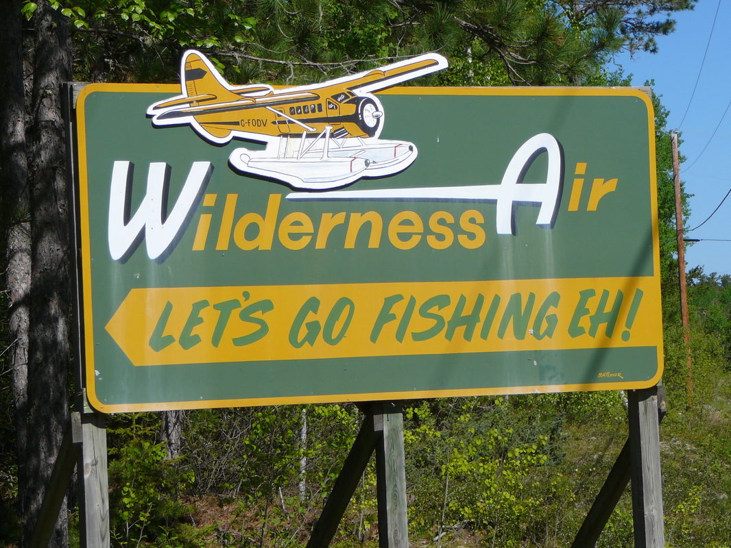
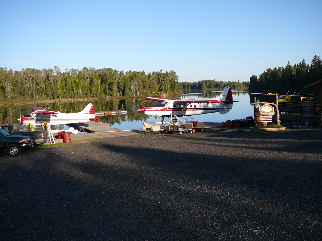
Vermilion Bay, known as Bold Eagle capitol, is an very small community on the junction of Highway 17 and highway 105 towards Red lake. A few kilometers before the junction take highway 647 north to the Wilderness Air seaplane base. It only takes a couple of minutes. Their sign-post is located on the left-hand side. Wilderness Air Escapes
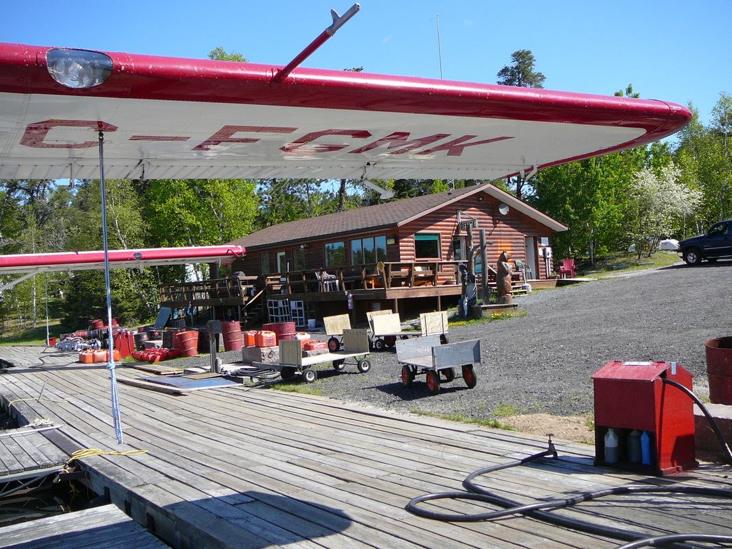
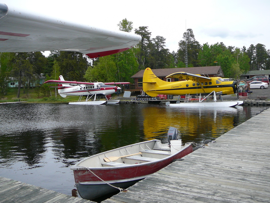
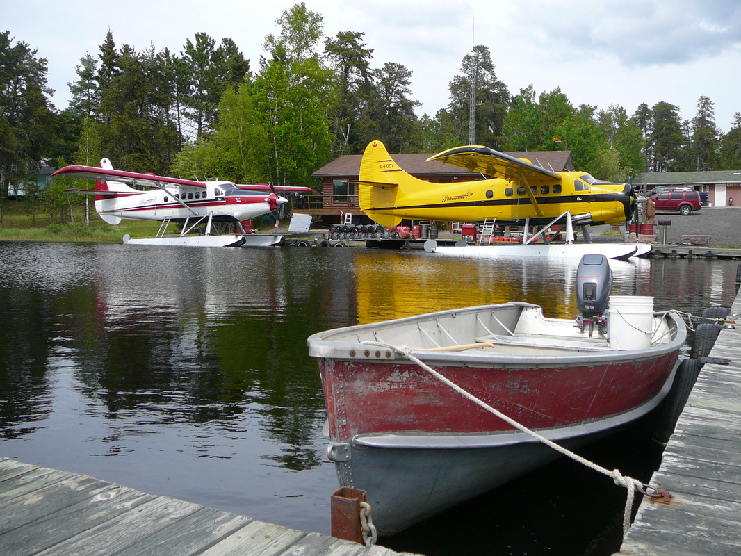
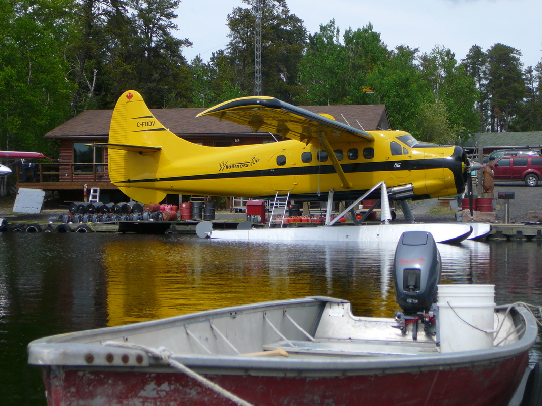
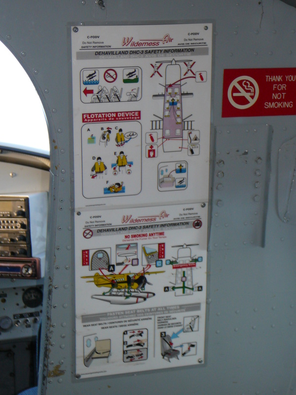
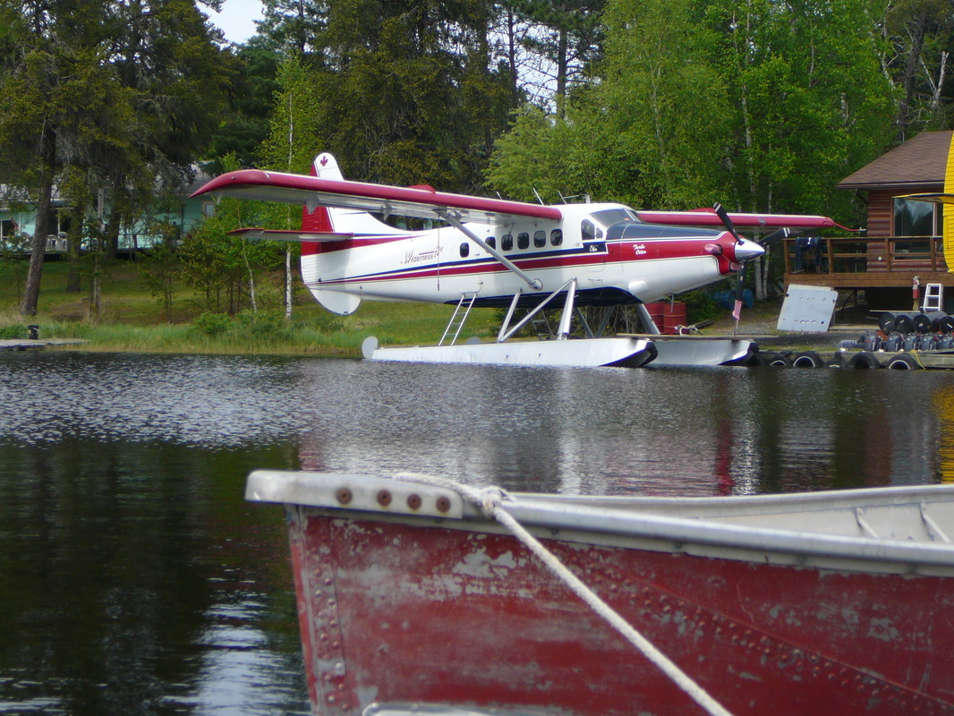
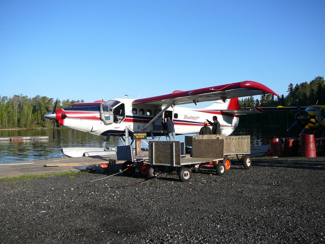
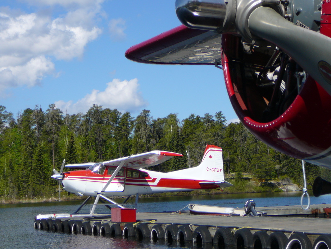
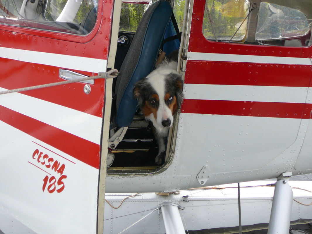
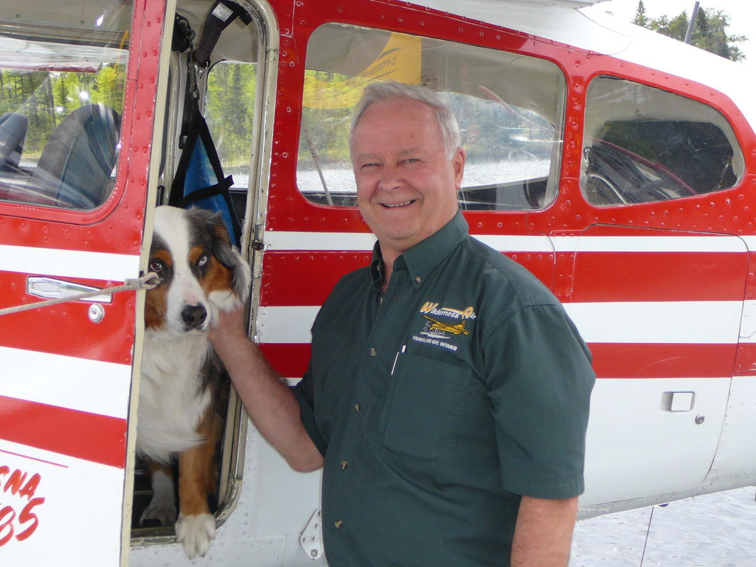
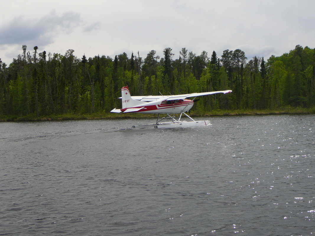
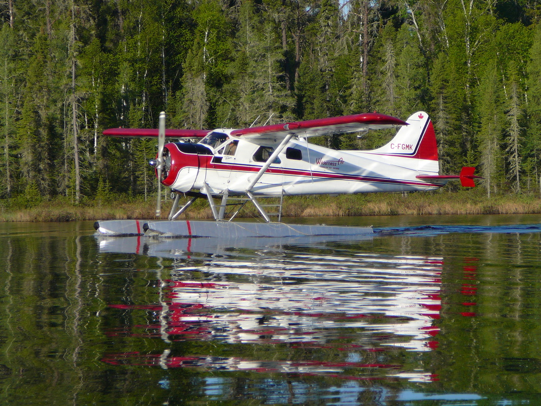
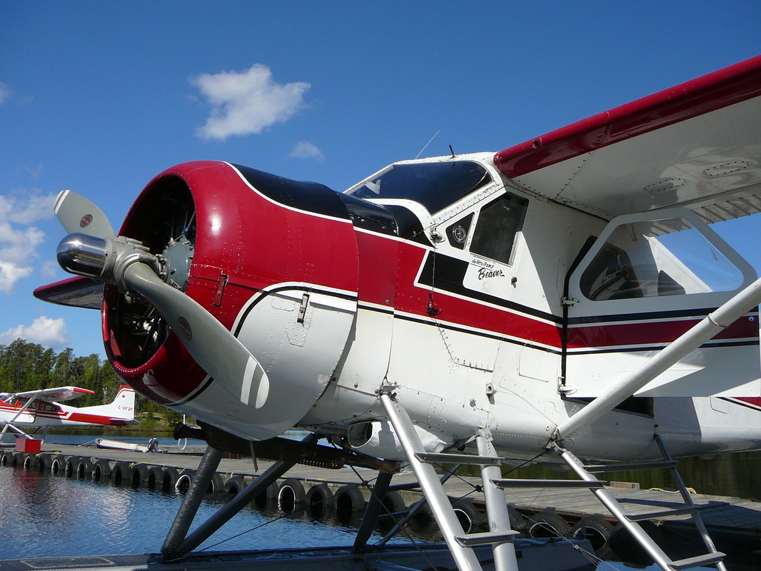
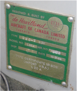
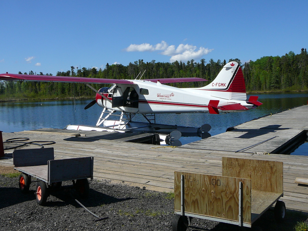
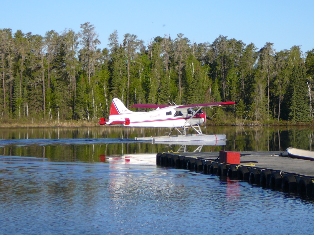
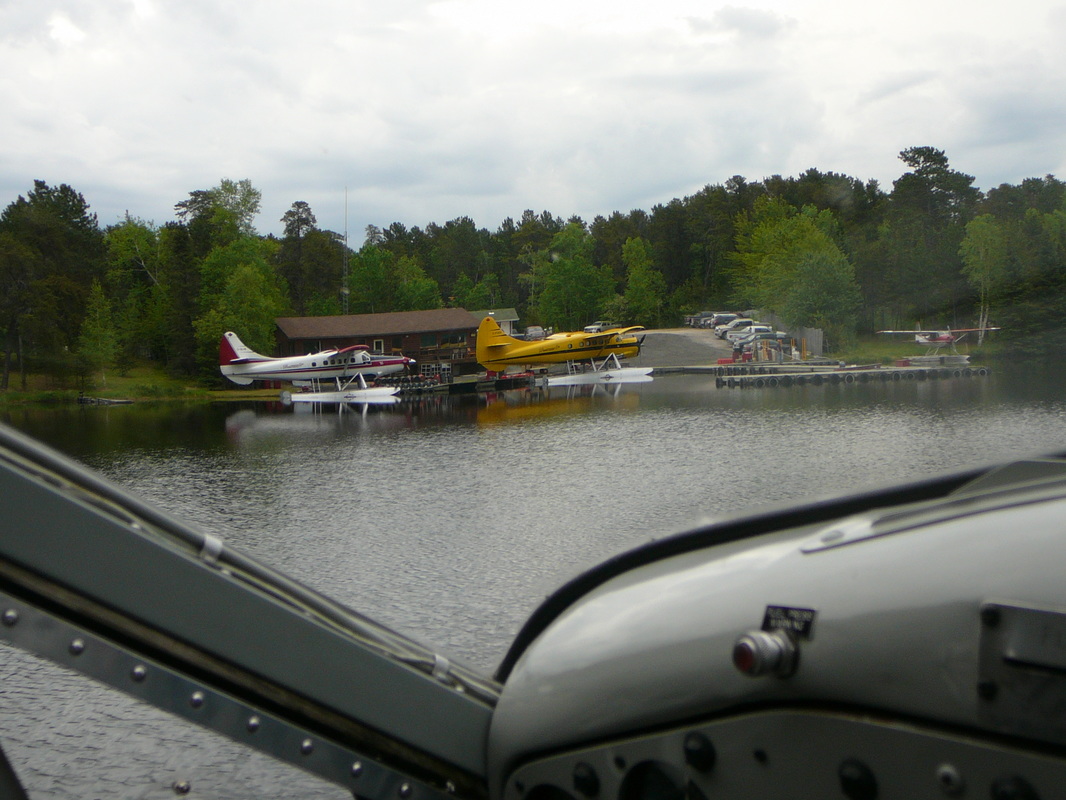
Wilderness Air Escapes seaplane base is ideally situated near the village of Vermilion Bay. The company’s owner and operator, Mr. Bob Huitikka, is an avid angler and pilot. He's been piloting anglers into the remote North since 1981 and knows all the best fishing holes! I talked to Bob and his staff comprehensively about their operation and their floatplanes. At Wilderness Air, they specialize in very remote fly-in fishing adventures! Or as Bob said; -“Fly with us and enjoy the splendor, serenity and exclusiveness of the remote wilderness experience. The remote Northern Ontario wilderness is truly stunning”. In 2000, his daughter Kelsey became part of the Wilderness Air Escapes team. Bob stated, - “You can expect and rely on excellent personalized service from all of our experienced bush pilots, like Herb Neufeld who is our Chief Pilot and has been with us for over 30 years. Wilderness Air's fleet of aircraft include two De Havilland Otters, three De Havilland Beavers and one Cessna 185. The fleet is serviced at their own maintenance facility. C-FODV DHC-3 Wilderness Air C-GLAB DHC-3 Wilderness Air C-FGMK DHC-2 Wilderness Air C-GFZF Cessna185E Wilderness Air C-FMEN Cessna180C private Check-out their brand-new site: www.wilderness-air-escapes.com
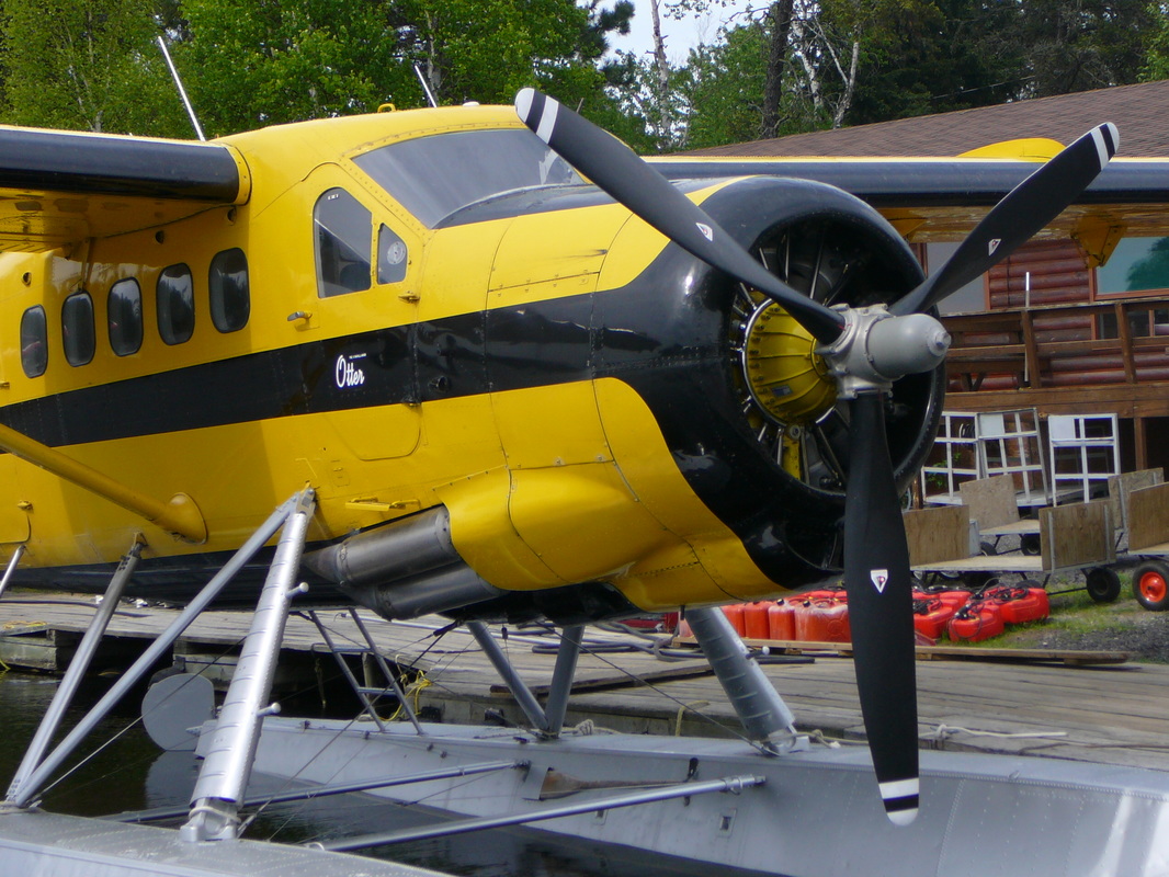
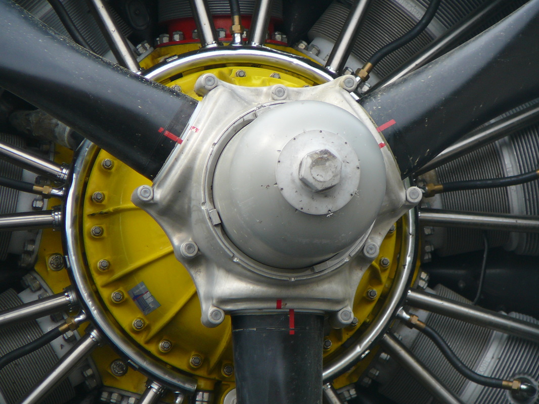
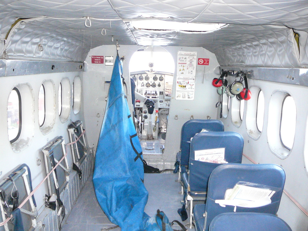
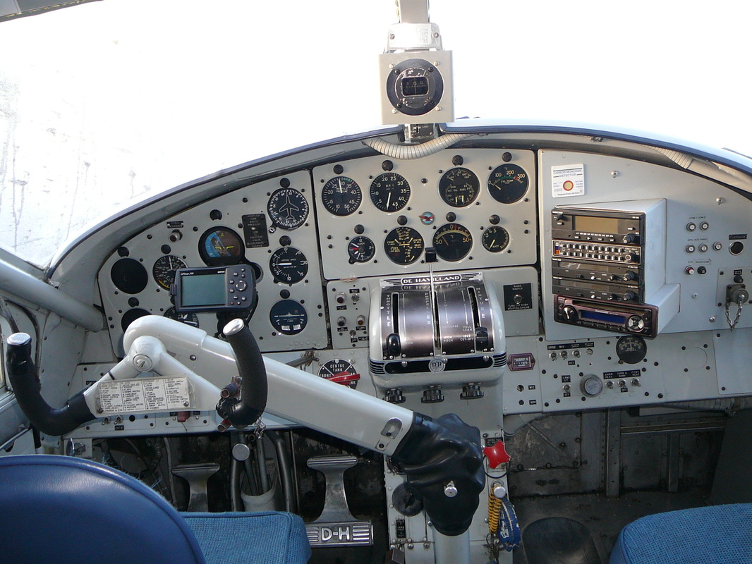
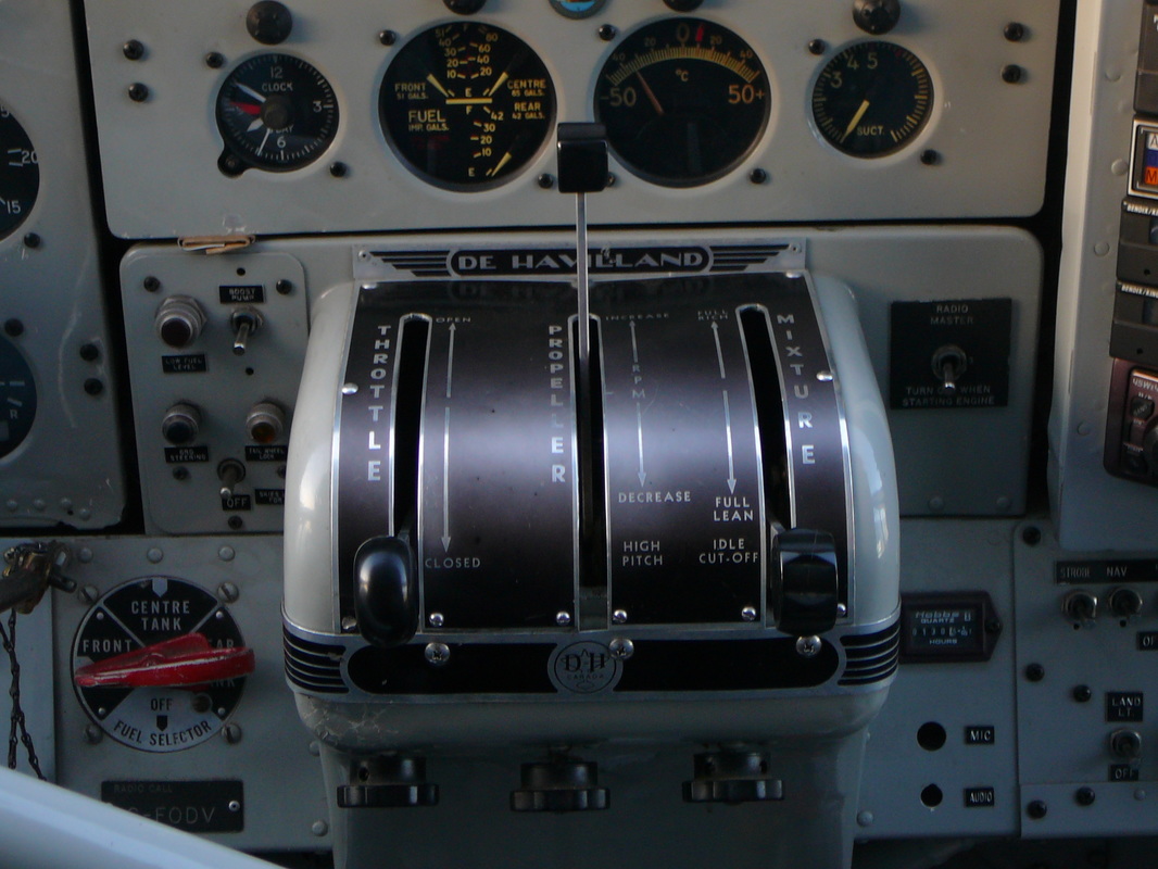
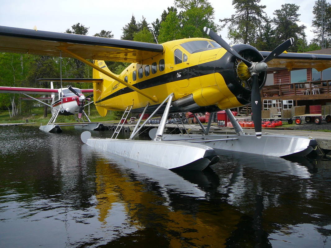
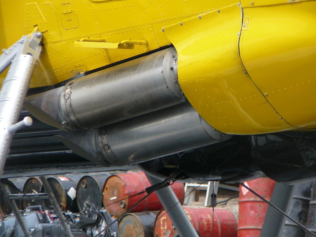
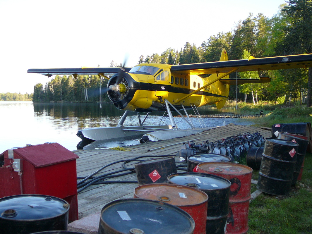
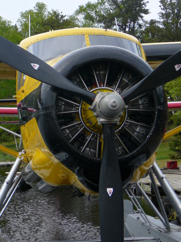
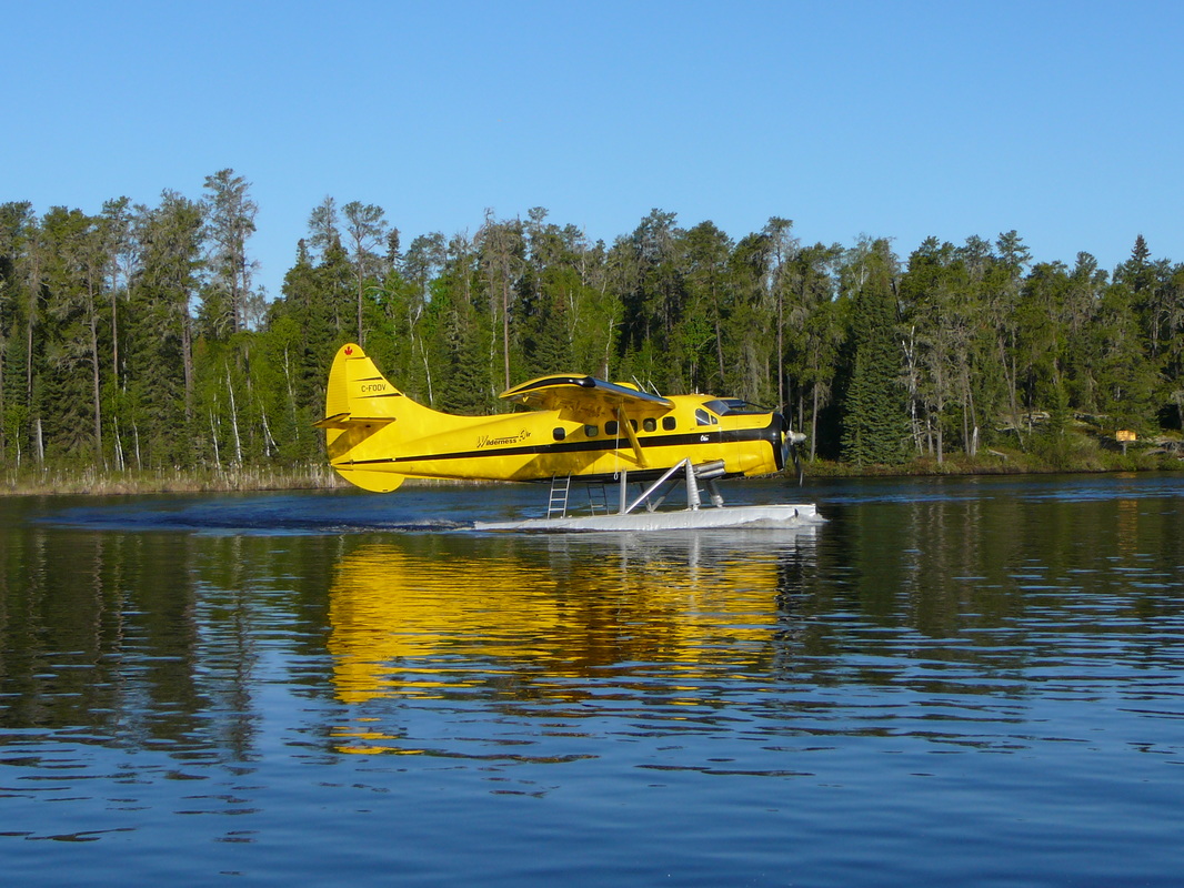
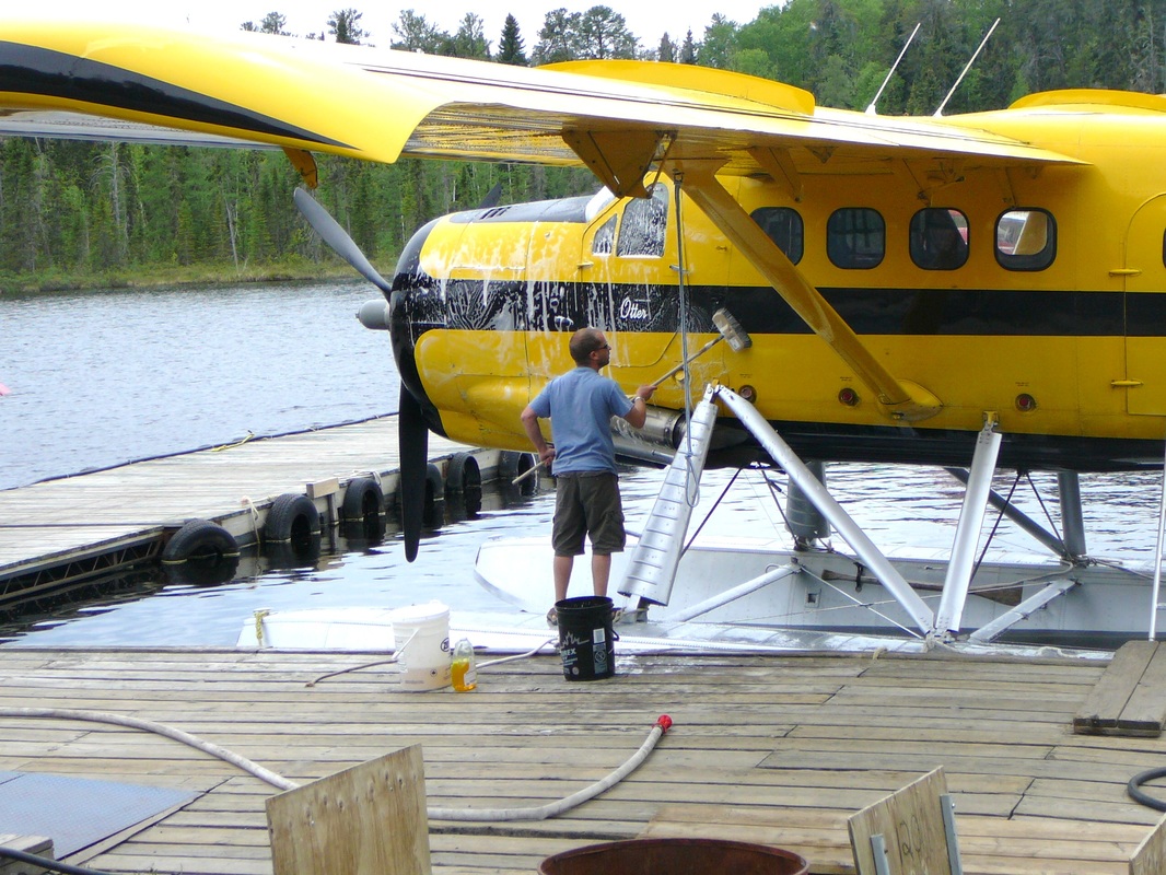
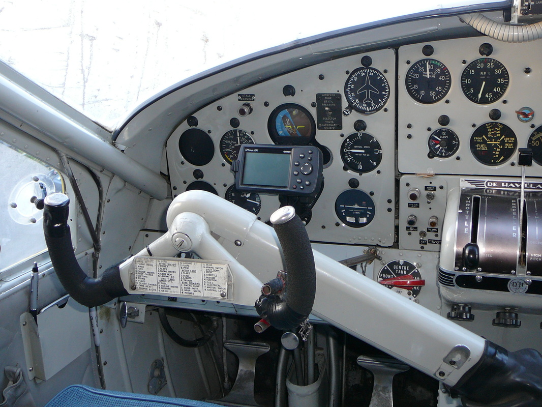
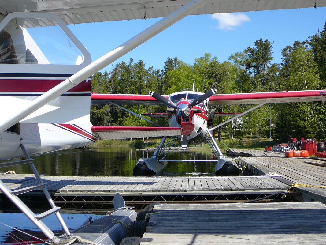
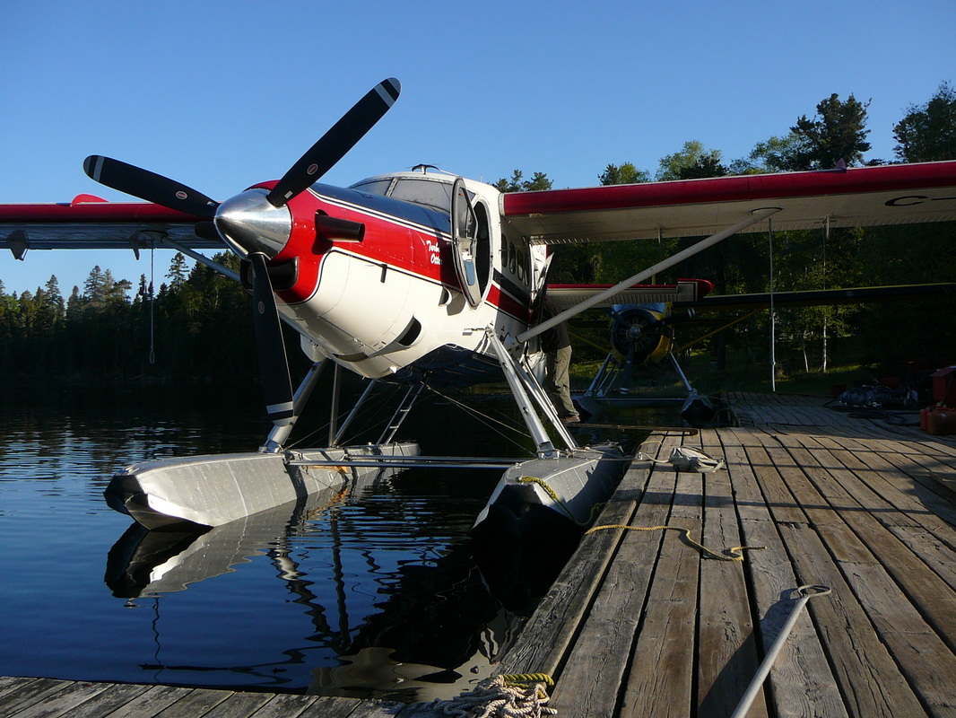
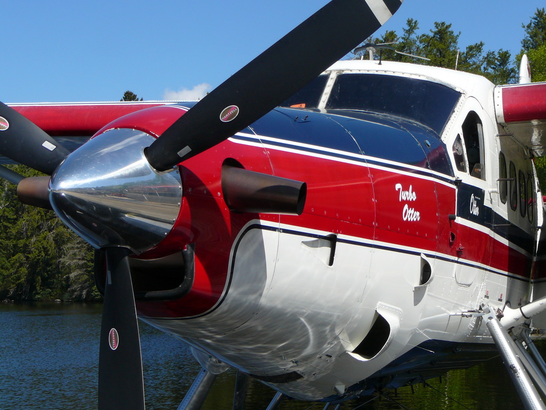
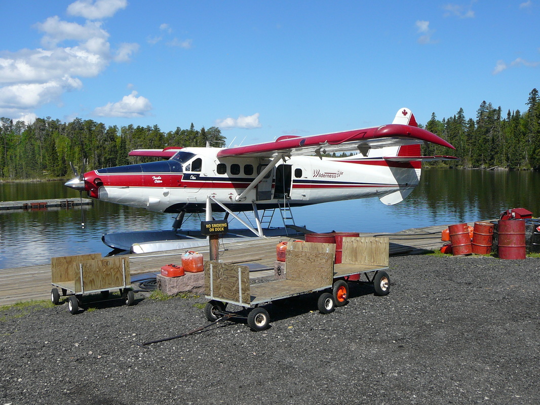
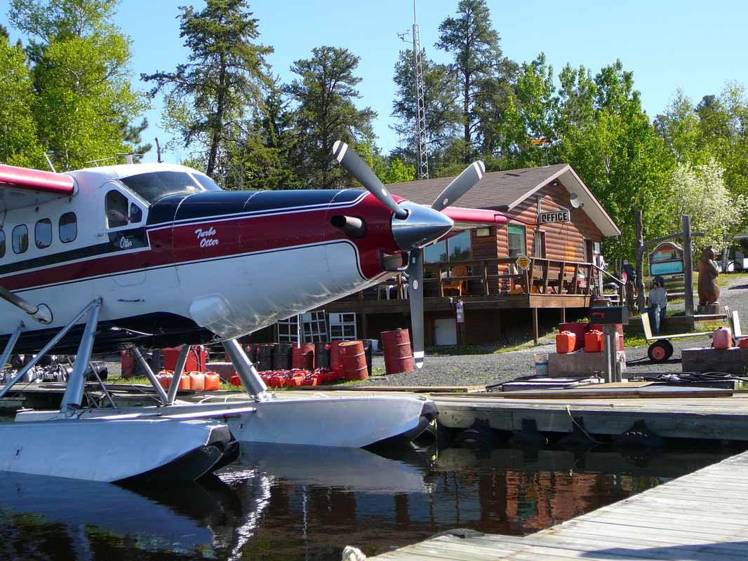
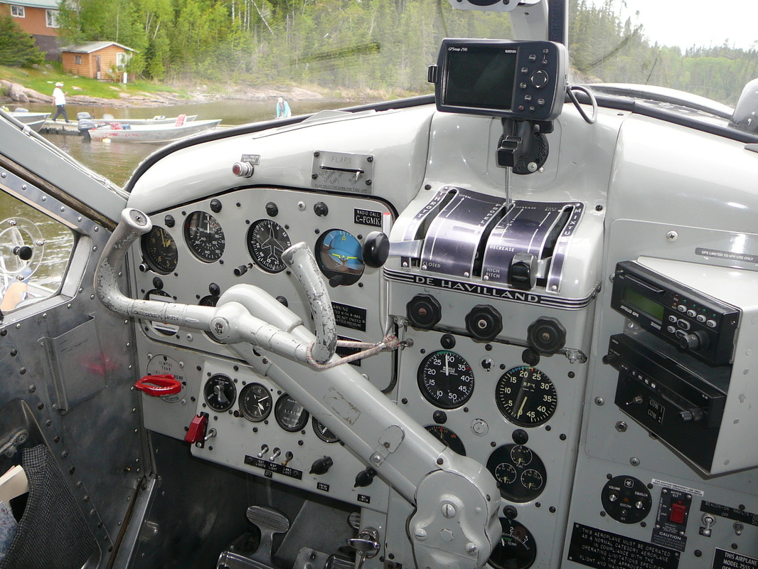
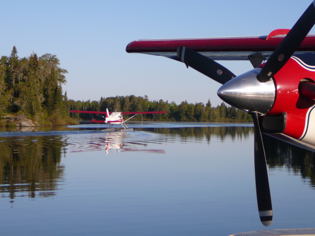
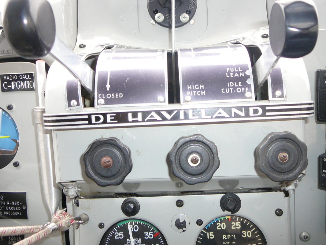
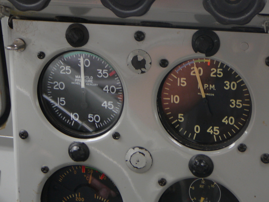
C-FODV Wilderness Otter ‘Delta-Victor’ warming the oil of her mighty Pratt & Whitney, in the early morning light. After oil temperature has reached 40 degrees Celsius (100 dgr. F) adjust to smoothest engine speed between 1200 to 1400 rpm. Mixture control FULL RICH. Hydromatic propeller – Leave at FULL INCREASE RPM. Note never rush engine warm-up. The de Havilland Canada DHC-3 Otter was designed in 1950 as the ‘big brother’ to the ubiquitous DHC-2 Beaver, with a total of 466 Otters having been built when production ceased in 1967. The high-wing construction of the Otter offers the bush operator a great advantage in being able to move alongside docks or swing-in over shorelines. The shallow float draught allows the aircraft to be taxied in close to the shore, facilitating the handling of cargo and/or passengers C-FODV, came off the production line in July 1961 for delivery to the Ontario Provincial Air Service (OPAS). The Otter faithfully served the Province for 25 years without an incident, until sold to Wilderness Air in 1986. In May 2000, C-FODV was joined by C-GLAB and the two Otters fly alongside the Beavers and the Cessna. The aircraft are used during the summer months bringing tourists into the Ontario wilderness areas. As of summer 2013, C-FODV was still painted in the basic all-yellow scheme it had carried during its time with the provincial government. Description of aircraft The DHC-3 Otter airplane is an all-metal, high wing monoplane powered by a single Pratt and Whitney Wasp engine driving a Hamilton Standard constant speed propeller. The aircraft has been designed to carry a pilot and from six to eleven passengers. Through partitions the aircraft is divided into a cockpit, a cabin and a baggage compartment. The general over-all dimensions of the airplane are; length 41 feet, 10 inches, wing spans 58 feet and height 12feet, 6 inches. The maximum gross weight of the aircraft is 7967 pound in seaplane configuration. The airplane is powered by a Pratt & Whitney Wasp R-1340, geared nine cylinders, air-cooled, radial, supercharged engine rated at 600 BHP. The supercharger is of the direct-connected, engine driven centrifugal type and is not under control of the pilot. The engine is burning 40 Imp. gallons per hour. The two exhaust augmentor tubes on both sides of the fuselage, just below the cockpit door, are a special design feature of the aircraft. In these four exhaust augmentor tubes, the exhaust gases produce suction strong enough to pull cooling air around the engine and from behind the engine accessories compartment while at the same time providing a measurable amount of thrust in cruising flight. The engine is thus effectively cooled during steep climbs when the forward air speed is low and engine output near its maximum. Engine controls. The throttle control lever at the left of the quadrant at the top of the pedestal slides in a gate marked CLOSED and OPEN. The lever is connected by a flexible cable and conduit control to the carburetor throttle valve. A friction control below the throttle lever prevents throttle creep when rotated clockwise. The fuel air mixture ratio is manually determined through the mixture control lever at the right of the quadrant. Reading from the rear to the front, positions marked on the quadrant gate are: IDLE CUT-OFF, FULL LEAN and FULL RICH. A friction control knob below the control lever prevents the control from creeping and permits to set any intermediate position, when tightened clockwise. Conventional engine instrument are mounted on a panel above the engine controls quadrant. They consist of; a tachometer, a manifold pressure gage, a cylinder head temperature gage, a carburetor mixture temperature gage, an oil pressure gage, an oil temperature gage and a fuel pressure gage. The tachometer indicator is operated by an electrical generator driven by the engine. A triple indicator fuel contents gage and a clock are also located on the engine instrument panel. The engine ignition switch is located on the starter panel below the pilot’s flight instrument panel. The switch is marked OFF, R, L and BOTH. The carburetor hot air control lever is located on the left side of the base of the pedestal and is mechanically linked to a barrel valve in the carburetor air intake. When the lever is in the COLD position, cold ram air enters the carburetor through the shielded air intake. As the lever is moved downwards towards the HOT position, the barrel valve progressively closes the ram air intake while it opens another duct. This second carburetor air duct allows heated air from the inside of a heat exchanger muff which surrounds a section of the engine exhaust collector, to mix with the cold ram air before delivery to the carburetor. Thus, intermediate positions of the lever between fully up and fully down give varying carburetor air intake temperatures. With the carburetor air control lever in the HOT position, the ram air intake is fully closed and hot air from the heat exchanger muff only is ducted to the carburetor. The resulting mixture temperature is indicated on the carburetor mixture temperature gage. The hand-operated cylinder primer pump injects fuel into cylinders numbers 1, 2 , 3, 8 and 9. It is located on the left side of the pedestal, below the engine controls quadrant. To unlock the primer, the pump handle is to be pushed in and rotated anti-clockwise. After use the primer pump handle must be relocked by pushing in and rotating clockwise in order to prevent engine flooding and a fire risk when the booster pump is switched on. The engine is started by an electrical, direct-cranking starter. The starter switch for the electrical direct-cranking starter motor and the two starter switches required for the electrical inertia starter are located on the starter panel below the flight instrument panel. The switch or switches are spring-loaded to the OFF position. A boost coil switch is located on the starter panel. This switch is also spring-loaded to the OFF position. The engine drives either a Hamilton Standard, three bladed, constant speed, counterweight type propeller or a Hamilton Standard, three bladed, hydromatic, non-feathering propeller. |
|
|
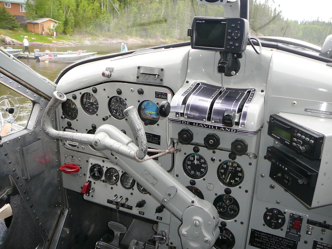
PROPELLER CONTROL The engine RPM are determined by the setting of the propeller control lever located on the quadrant on top of the pedestal. The control lever is connected to the propeller governor by a flexible cable and slides in a gate marked HIGH PITCH, DECREASE RPM and INCREASE RPM. The propeller governor automatically maintains any selected rpm within the operating range of the propeller, regardless of variation in air loads or flight attitudes. A friction control below the propeller control lever prevents the lever from creeping when rotated clockwise. The governor maintains the propeller blades within the constant speed range by supplying oil at engine pressure to the outboard end of the propeller actuating piston which, together with the centrifugal twisting moment acting on the blades, tends to move the blades towards low pitch. To balance the effect of both these forces, engine oil is boosted in pressure by the engine driven propeller governor and is passed to the inboard end of the propeller actuating piston to the blades towards high pitch. The propeller pitch can be changed by reselection of the propeller control lever which varies the load on the governor fly-weight and allows the governor pilot valve to take up a new position to maintain the propeller at the new selected constant speed setting. |
|
The oil tank, which is of 9 Imp. gal. (40,5 liters) capacity is located under the cockpit floor. Servicing of the oil tank is done through a filler neck on the left side of the fuselage. The oil cooler with an integral surge relief valve and a thermostatic by-pass valve is located behind the firewall and has its own air-flow system.
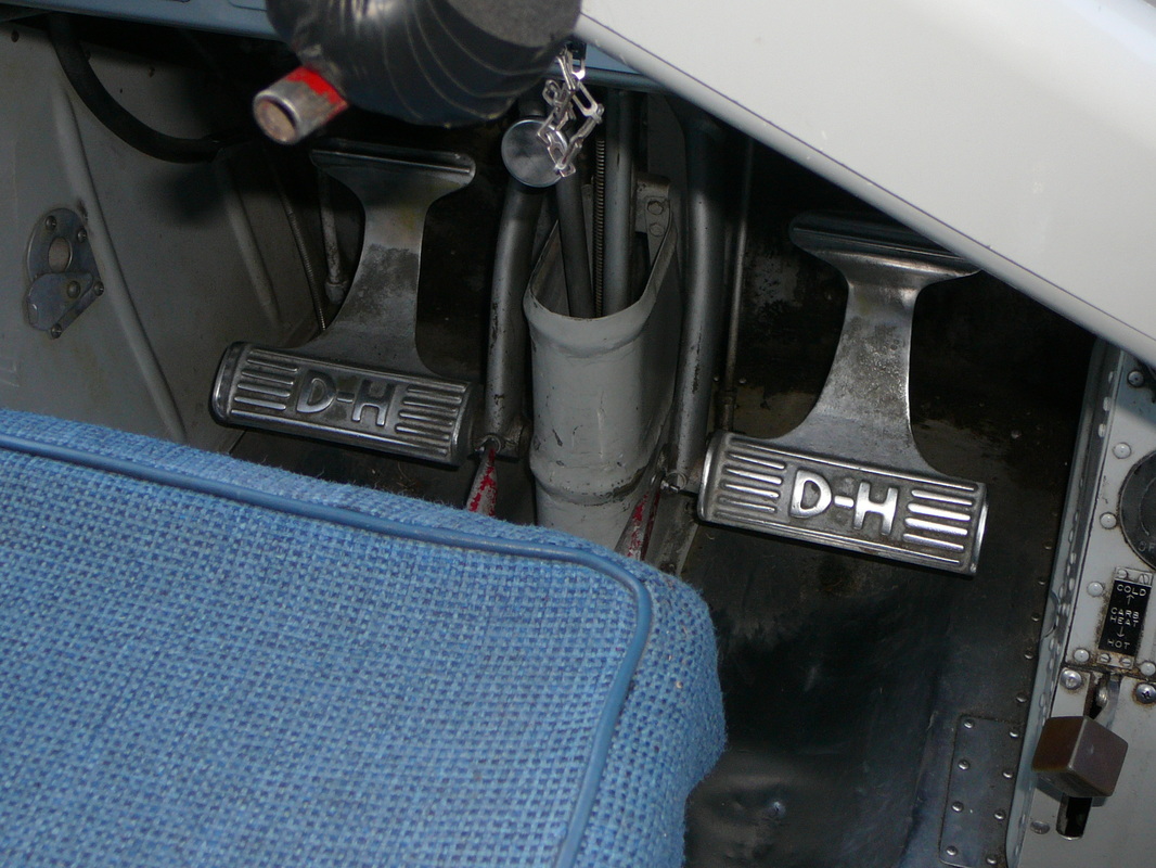
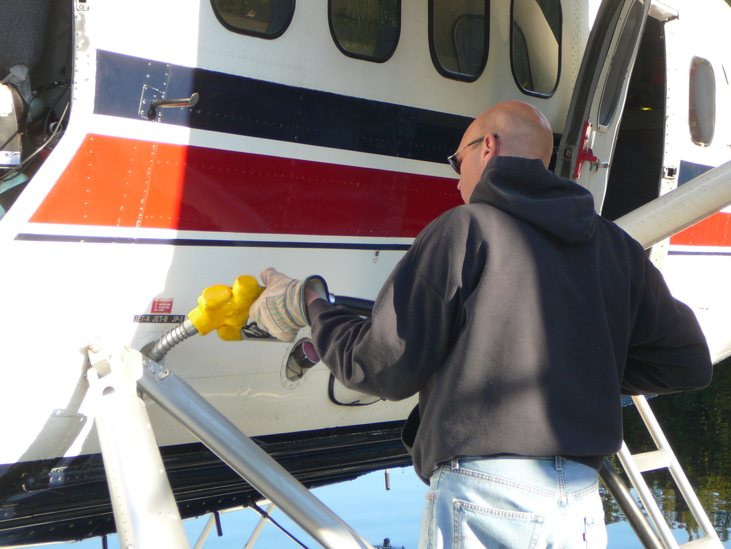
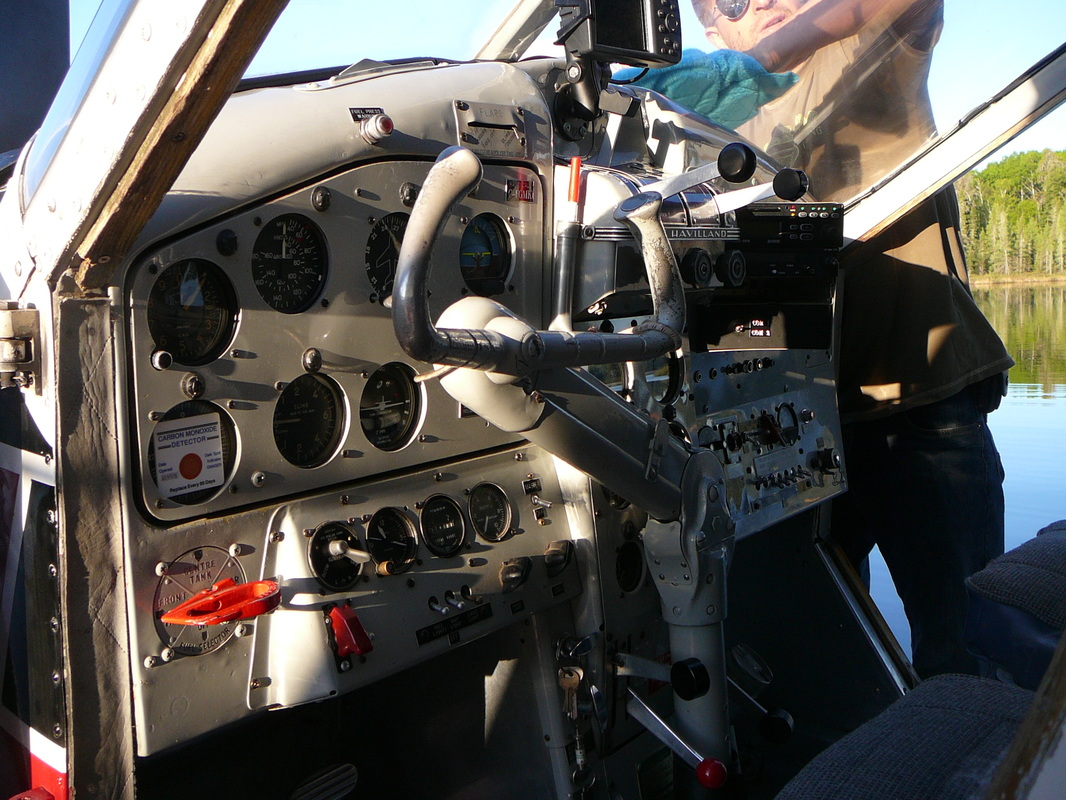
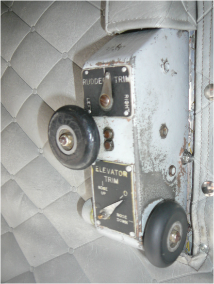
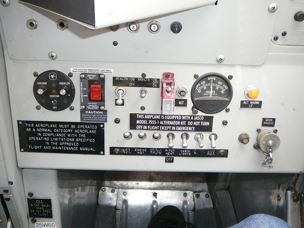
Fuel is contained in three flexible bag-type tanks beneath the forward portion fo the cabin floor. The tanks are buttoned with fasteners to the underside of the floor, to stringers and the skin of the fuselage. The tank capacity is as follows; front tank 51 Imp. Gal (233 liters), center 85 Imp. Gal (389 liters) and the rear tank 42 Imp. Gal. (192 liters). The center tank consists of two interconnected cells. Each of the three tanks is used separately, the fuel flow to the engine being controlled by the fuel selector valve. An electrically-operated booster pump ensures that an adequate fuel flow is maintained in the event of failure of the engine driven pump. The fuel selector handle, located below the bottom right corner of the pilots instrument panel, can be positioned to FRONT TANK, CENTER, REAR TANK or OFF. When the engine is not operating, the selector handle must be selected to OFF to prevent drainage of the fuel supply line into the tank. The fuel booster pump switch is located on a panel to the left of the engine controls quadrant. A combined fuel pressure, oil pressure and oil temperature gage is located on the engine instrument panel above the engine controls quadrant. The triple indicator fuel contents gage, graduated either in Imperial or U.S. gallons, will indicate only when the FUEL CONTENTS circuit-breaker is set. This switch is located on the junction box circuit-breaker panel, behind the copilot’s seat. A warning light gives an indication of low fuel level in the tank from which the engine is operating. The light becomes illuminated when fuel for approximately 15 minutes of cruising remains in the tank. The shut-off control handle stops the supply of both fuel and oil to the engine in case of emergency. It is located on the right side of the pedestal, below the engine controls quadrant. Electrical energy is supplied by a direct current 50 amp. 28-30 volt generator in conjunction with a 24 volt 24 amp-hr. storage battery. Installations of generators of 80 to 100 amp. and batteries up to 35 amp-hr. have been made. All circuits of the electrical system are protected by manual reset-type circuit-breakers on the junction box panel behind the co-pilot’s seat or on the electrical switch panel on the co-pilot’s sub-panel. The battery is inside the baggage compartment on a shelf in the rear right-hand corner. The following equipment and controls are supplied by the electrical system; engine starter, booster coil, fuel booster pump, pitot head heater, engine fire ext. system, instrument and warning lights, interior lights, navigation lights, landing lights, heater installation, radio and communication equipment. For starting the engine or for electrical ground checks, an external power source may be connected to an external power receptacle fitted to the right side of the fuselage, aft of the cabin door. Access is gained through a spring-loaded hinge panel. When external power is connected, the aircraft battery is isolated if the battery master switch is in the OFF position. The battery master switch on the starter panel, is of the double-pole, single-throw type and serves also as the generator field switch. A volt-ammeter is on the electrical switch panel. The instrument constantly shows the number amps. being delivered to the system and the battery. When pressing the button on the left side of the instrument, the generator output voltage is indicated. All control surfaces are mass-balanced and are conventionally operated by a control column and rudder pedals. The handwheel portion of the control column may be ‘thrown-over’ for use by a co-pilot, in conjunction with the installation of rudder pedals on the right side of the cockpit. The wing flaps are of the full-span, double-slotted type. The outboard trailing edge portions of the flaps are operated independently as ailerons. The incidence of the tailplane may be adjusted in flight by rotating the TAILPANE TRIM handwheel at the right side of the pilot’s seat. The handwheel operates in the natural sense and its pointer moves over a label marked NOSE DOWN, TAKE OFF SETTING and NOSE UP. The area marked TAKE OFF SETTING is edged in green. The neutral position of the tail-plane trim is marked 0 with further markings to 2 in the NOSE DOWN direction and to 5 in the NOSE UP direction. The rudder trim tab is actuated by a handwheel in the cockpit roof. The handwheel assembly incorporates a position indicator which moves over a scale marked L and R indicating the direction an amount of trim applied. The aileron trim which is adjusted by means of a handwheel on the control column varies the tension left or right of the aileron control cable in flight. Fixed trim tabs on each aileron are provided for adjustment on the ground by qualified servicing personnel. The pilot’s rudder pedals may be adjusted for leg reach. By pulling the adjusting knob, the pedals can be moved to the desired position and secured in that position by releasing the adjusting knob. The wing flaps are operated hydraulically by a flap actuating jack assembly, located in the fuselage roof between the front and rear wing attachment lugs. Hydraulic fluid, contained in a separate reservoir located aft of the firewall on the left-hand side, is pumped into the flap actuating jack assembly by means of a handpump located beneath the pilot’s seat. Wing flaps are selected UP or DOWN with a selector lever and after they are pumped to the desired position with the handpump, they are automatically locked by a hydraulic ratchet valve which is part of the flap actuating jack assembly. The wing flaps are mechanically connected to the trim tab on the left elevator so that actuation of the wing flaps automatically deflects the trim tab to maintain the longitudinal trim. The handpump lever is in line with the right-hand side of the pilot’s seat and is operated in a fore-and-aft movement. The wing flaps selector lever is mounted on the tailplane trim pedestal, to the right of the pilot’s seat. CRUISE, LAND, or intermediate positions of the wing flaps are obtained by moving the wing flaps selector lever to up or down position and then pumping the flaps to the desired position, as shown on the wing flaps position indicator. Note when the wing flaps have been pumped to the desired position, the wing flaps selector lever should immediately be moved to its neutral position, to provide an addition lock on flap motion. The wing flaps position indicator is located on the vertical frame member of the windshield and is marked UP, CRUISE, CLIMB, TAKE-OFF, LAND and DOWN. A shock-mounted flight instrument panel is provided for the pilot and incorporates the following flight instruments; Airspeed Indicator, Altimeter, Artificial Horizon, Directional Gyro, Rate-of-Climb Indicator, Turn-and-Bank Indicator, Magnetic Compass, Radio Compass and space provision for another flight or Navigation Instruments like a GPS. Pitot-Static operated instruments comprise: Airspeed Indicator, Altimeter and Rate-of-Climb Indicator. The engine driven vacuum pump provides suction to operate; Directional Gyro, Artificial Horizon and Turn-and-Bank Indicator. The artificial horizon is operated by the vacuum system and gives bank, dive and climb indications. A knob at the bottom of the instrument dial adjusts the vertical position of the miniature airplane for fore-and-aft attitudes of the airplane. A caging knob permits to lock the instrument in the upright position and provides a rapid means for resetting if the operating limits of the instruments are exceeded. The operating limits are set to permit 60 degrees climbs and glides and 100 degrees right of left banks before the limit stops are reached. The suction gage is located on the engine instruments panel. The gage is calibrated from zero to 10 in. Hg. The outside air temperature gage is located in the cockpit roof. It is of the direct-reading bulb type. Its dial is graduated in degrees Fahrenheit and Centigrade. The engine fire extinguisher system is controlled from the fire extinguisher panel below the flight instrument panel. The system incorporate a fire extinguisher bottle, flame switch and a length of fuse wire located in the engine compartment. In the event of fire, a red warning light on the extinguisher panel is illuminated and the EXTINGUISHER SWITCH must be switched on to discharge the bottle after the engine is shut down. Both the warning light and the extinguisher circuits are protected by push-to-reset button type circuit-breakers on the fire extinguisher panel. A hand-operated fire extinguisher in a quick release clip is attached to a bracket to the left and rear of the pilot’s seat. A first-aid kit is stowed in a bag located on the right-hand cabin side between the passenger door and the rear cabin bulkhead, aft and above the door lock. A second first aid kit may be installed behind the pilot’s seat in the cockpit. A 27-inch diameter hatch has been provided in the rear cabin floor just aft of the rear cabin bulkhead normally closed by lids screwed to the floor and out skin of the fuselage. A trap door may be installed. The cabin side seats may be folded flat against the wall, flush with the base of the heater duct. The rear seat hinges up against the rear cabin bulkhead. All seats have padded backs, buoyant seat cushions and lap safety belts. Fourteen cargo tie-down rings, eight of which are permanently installed are supplied with each aircraft. Eighteen receptacles to receive the six removable cargo tie-down rings permit to secure any type of cargo. An additional number of receptacles may be provided. Relief tube may be installed in the cockpit on the right-hand side of the pedestal and in the cabin. The relief tube for the cabin is located in the baggage compartment. |
|
|
Cessna 180s and 185s
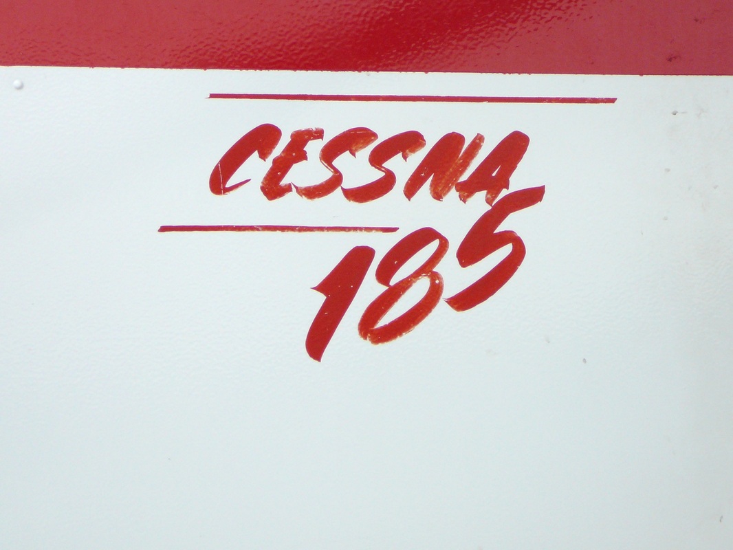
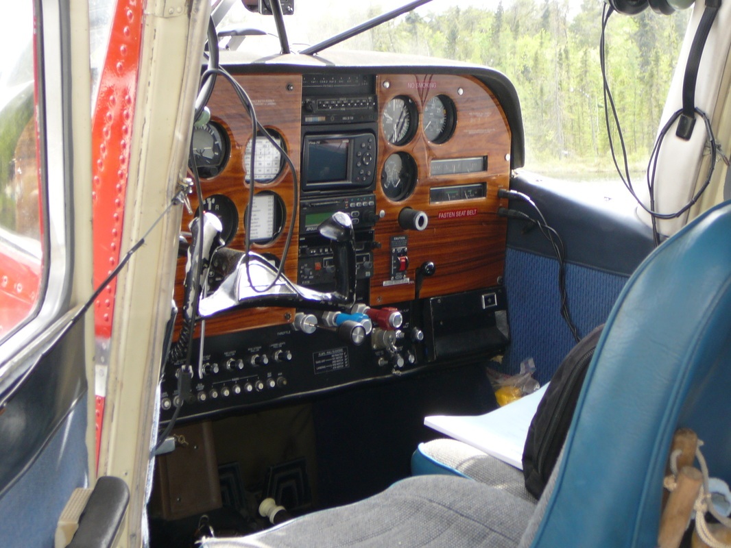
Along with the Super Cub, the Cessna 180, eventually came to be known as the Skywagon and the 185, which came to bear the name Skylane, are considered to be prime bush planes. Cessna began production of the 180 in 1953 as an up-powered development of the Cessna 170. Both aircraft featured conventional landing gear and both were eventually fitted with tri-cycle landing gear (becoming the 172 and 182 respectively). Cessna introduced the 185 in 1961 as a more powerful version of the 180. The 180 and 185 are very similar in appearance, but the 185 has a larger dorsal fin attached to its vertical tail. Like the Super Cub, Cessna 180s and 185s are easily fitted with floats, skis or tundra tires. Cessna ceased producing the 180 in 1981. Production of the 185 ceased in 1985. Though the design is no longer in production, many of these aircraft are still in use as personal aircraft and in utility roles such as bush flying Preflight Inspection of the Cessna 180K Visually check airplane for general condition during walk-around inspection. In cold weather, remove even small accumulations of frost, ice or snow from wing, tail and control surfaces. Also, make sure that control surfaces contain no internal accumulations of ice or debris. Prior to flight, check that pitot heater (if installed) is warm to touch with 30 seconds with battery and pitot heat switches on. If a night flight as planned, check operation of all lights and make sure a flashlight is available. CABIN Pilot’s Operating Handbook – Available in the airplane. Control Wheel Lock – REMOVE. Ignition Switch – OFF. Avionics Power Switch – OFF. Master Switch – ON. Fuel Quantity Indicators – CHECK QUANTITY. Master Switch – OFF. Static Pressure Alternate Source Valve – OFF. Fuel Selector Valve – BOTH ON. Baggage Door – CHECK securely locked. EMPENNAGE Rudder Gust Lock – REMOVE. Floats – Drained and Check for damage. Control Surface – CHECK freedom of movement and security. RIGHT WING TRAILING EDGE Aileron – CHECK freedom of movement and security. RIGHT WING Wing Tie-Down – DISCONNECT. Fuel Tank Vent Opening – CHECK for stoppage. Before first flight of the day and after each refueling, use sampler cur and drain small quantity of fuel from fuel tank sump quick-drain valve and fuel line quick-drain valve (located on bottom of fuselage below the cabin door) to check for water, sediment and proper fuel grade. Fuel Quantity – CHECK VISUALLY for desired level. Fuel Filler Cap – SECURE and vent unobstructed. NOSE Static Source Openings (both sides of fuselage) – CHECK for stoppage. Propeller and Spinner – CHECK for nicks, security and oil leaks. Carburetor Air Filter – CHEK for restrictions by dust or other foreign matter. Engine Oil Level – CHECK. Do not operate with less than nine quarts. Fill to twelve quarts for extended flight. Before first flight of the day and after each refueling, use sampler cur and drain small quantity of fuel from fuel tank sump quick-drain valve and fuel line quick-drain valve (located on bottom of fuselage below the cabin door) to check for water, sediment and proper fuel grade. LEFT WING Fuel Quantity – CHECK VISUALLY for desired level. Fuel Filler Cap – SECURE and vent unobstructed. Before first flight of the day and after each refueling, use sampler cur and drain small quantity of fuel from fuel tank sump quick-drain valve and fuel line quick-drain valve (located on bottom of fuselage below the cabin door) to check for water, sediment and proper fuel grade. LEFT WING Leading Edge Pitot Tube Cover – REMOVE and check opening for stoppage. Stall Warning Opening – CHECK for stoppage. To check the system, place a clean handkerchief over the vent opening and apply suction; a sound from the warning horn will confirm system operation. Fuel Tank Vent Opening – CHECK for stoppage. Wing Tie-Down – DISCONNECT. LEFT WING Trailing Edge Aileron – CHECK freedom of movement and security. STARTING ENGINE Mixture – RICH. Propeller – HIGH RPM. Carburetor Heat – COLD. Throttle – OPEN ½ inch. Prime – AS REQUIRED. Master Switch – ON. Propeller Area – CLEAR. Ignition Switch – START (release when engine starts). Oil Pressure – CHECK. TAKE-OFF Wing Flaps – 0° or 20°. Cowl Flaps – OPEN. Carburetor Heat – COLD. Power – FULL THROTTLE and 2400 RPM Elevator Control – MODERATE TAIL LOW. Climb Speed – 85 KIAS. Wing Flaps – UP after obstacles are cleared. |
|
The wing flaps of the Beaver are of the slotted type and extend from the wing roots to the inboard ends of the ailerons which also droop in conjunction with the flap movements. The flaps are operated by an actuating cylinder located in the fuselage at the left-hand wing root. Hydraulic fluid is supplied to the actuating cylinder by a hand pump, under the pilot’s seat. This hand pump has an integral reservoir, a selector valve and a relief valve. The relief valve is set at 1,000 psi. The wing flap hand pump lever is at the right-hand side of the pilot’s seat and is operated in a fore-and-aft direction.
|
Meet-and-greet with Mr. Robbie Robinson
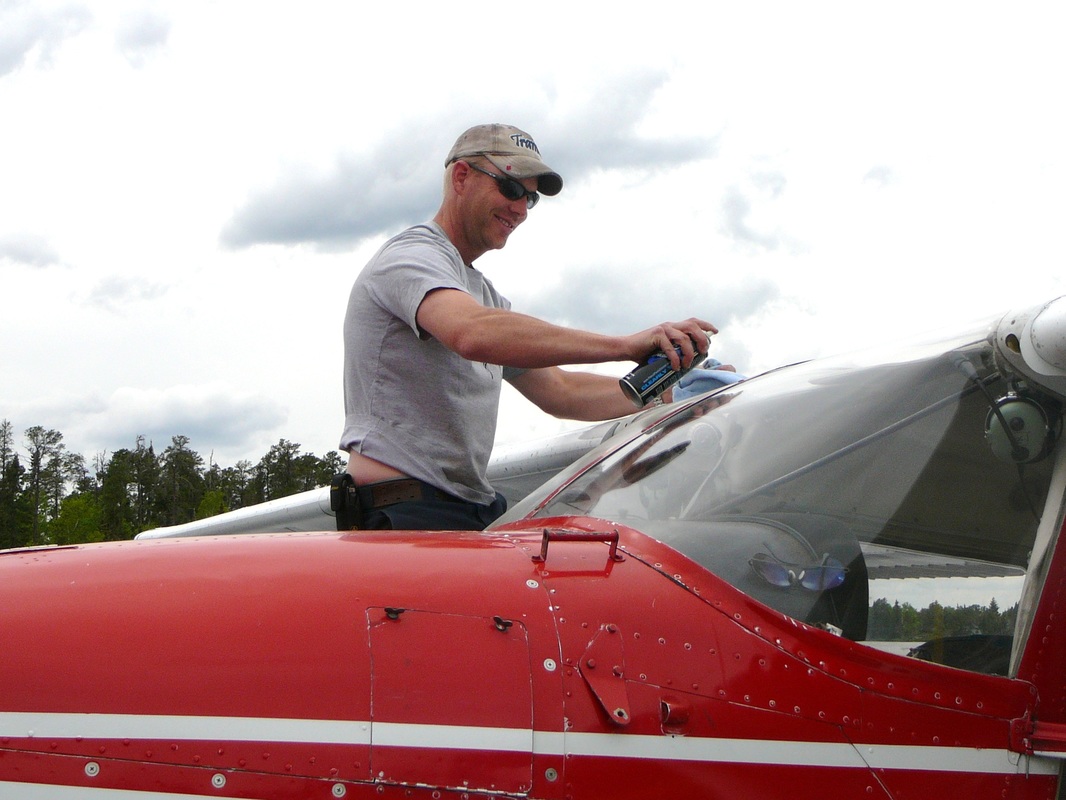
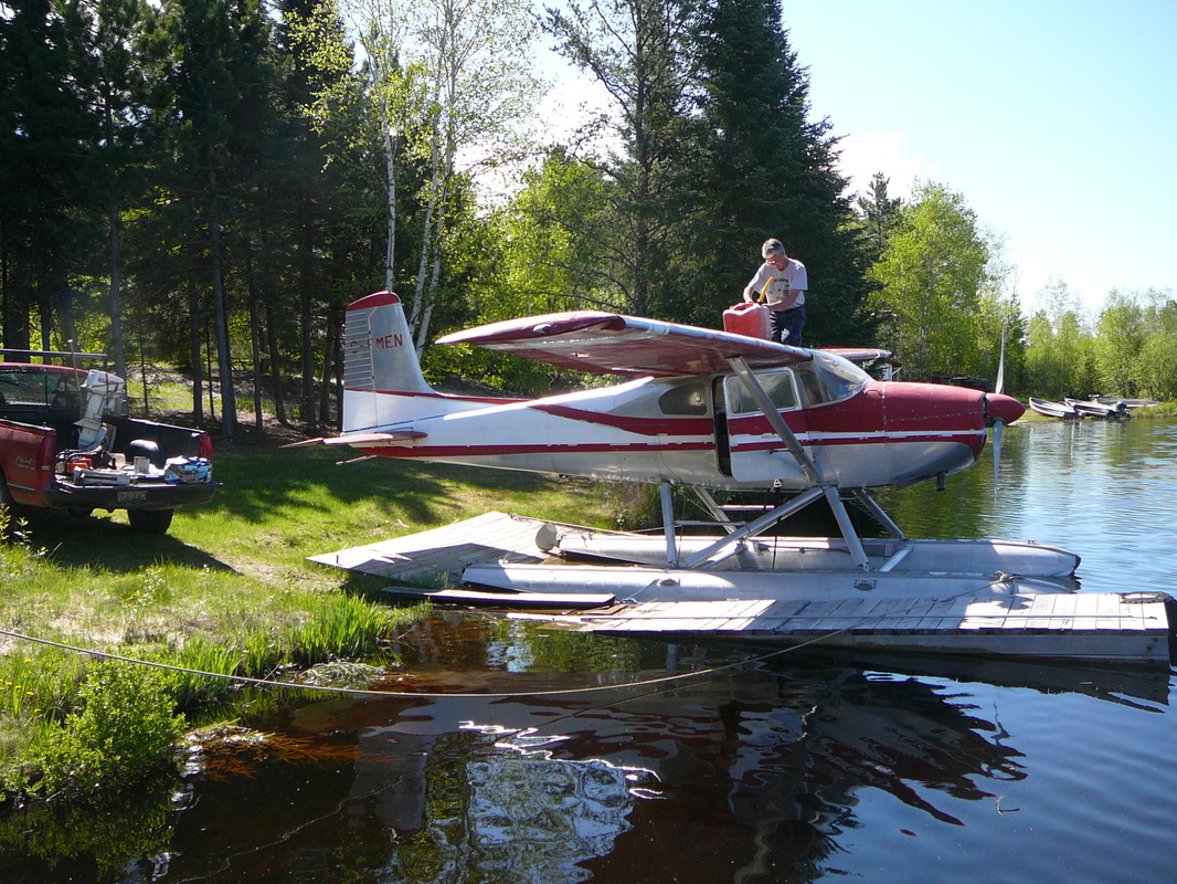
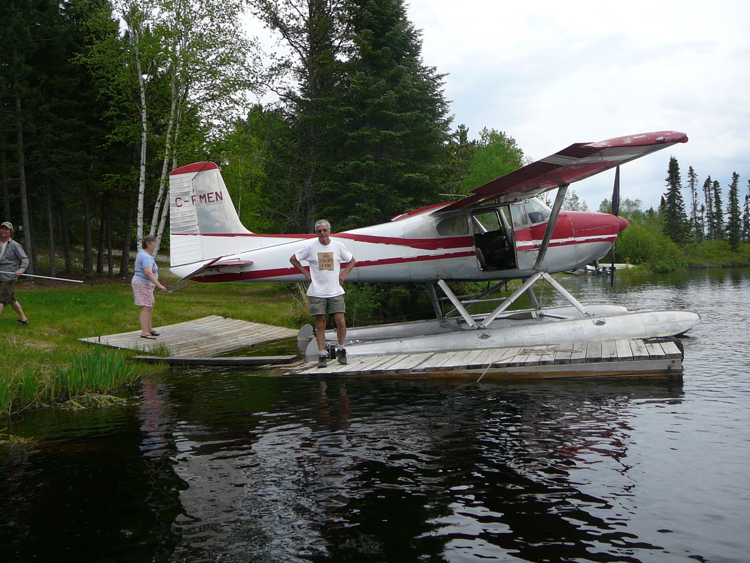
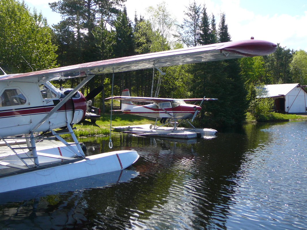
During our stay at Wilderness Air I got acquainted with a very kind man who was servicing his Cessna 180 (CF-MEM), which was docked just next door to the Wilderness Air base. The man appeared to be Robbie Robinson. Robbie owned Wilderness Air between the late 1960's until 1982 when he sold the business (airplanes and cabins) to Bob Huitikka, who still owns Wilderness Air. During these years ‘Echo-Mike’ was part of the Wilderness Air fleet but Robbie did not sold his faithful 180. ‘Echo-Mike’ is docked next door to Wilderness Air as Robbie and his wife live right next door his former company! According Bob Huitikka, ‘Echo-Mike’ is the best 180 in Ontario! |
|
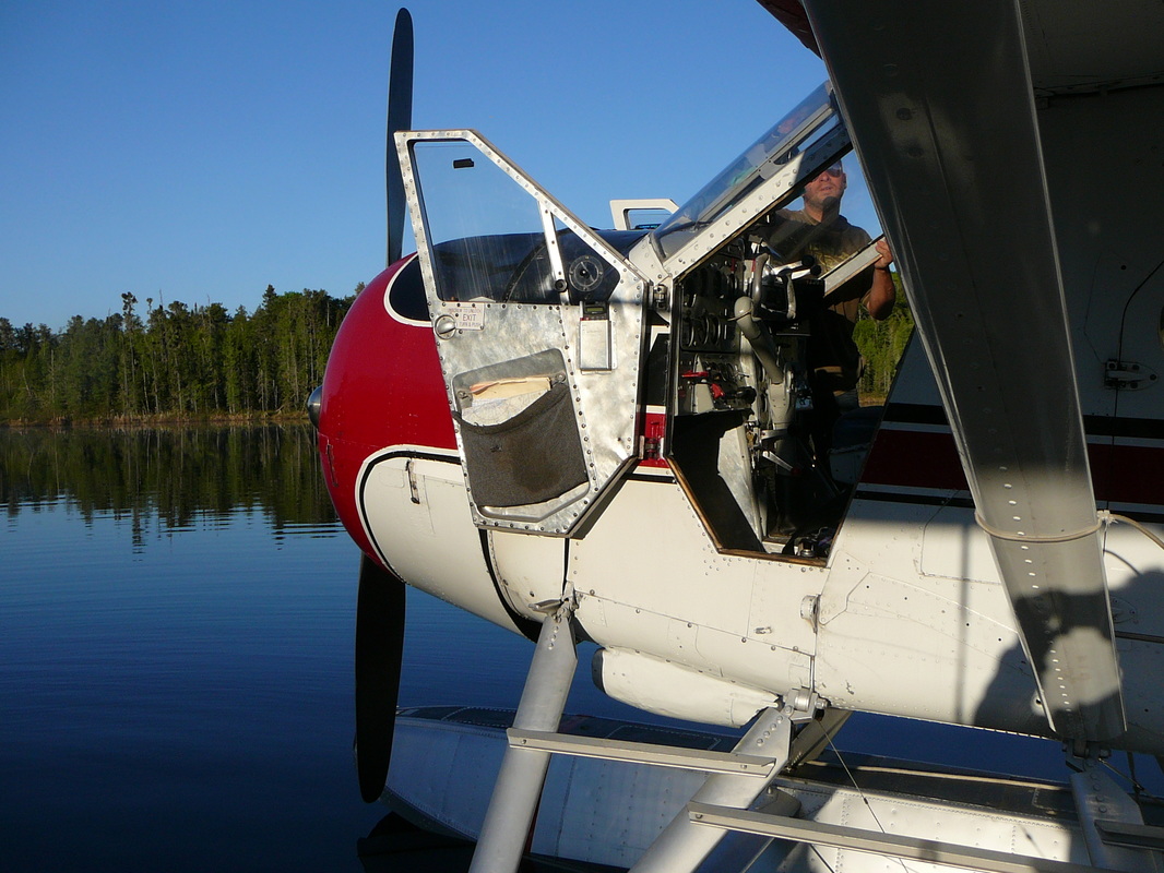
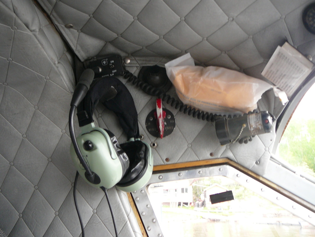
The emergency shut-off lever, on the right side of the pedestal, below the engine instrument panel, is normally wire locked in the down position. When pulled sharply up to break the wire lock and moved to the closed position, it cuts off the supply of both fuel and oil to the engine. The starter switch for the electric direct cranking starter motor and the starter clutch and boost coil switches required for the electrical inertia starter are located on the starter panel below the flight instrument panel. A boost coil switch, located on the starter panel, is spring-loaded to the OFF position. A triple indicator fuel contents gauge, located on the right side of the engine instrument panel, is graduated in Imperial gallons, in white and red figures for in-flight and tail down position respectively. Fuel is contained in three tanks under the cabin floor which are used separately. They are serviced through three filler necks in a filler compartment protected by a hinged door on the forward left-hand side of the fuselage, adjacent to the cockpit door. Fuel is supplied from any one of the three fuel tanks by selecting FRONT-TANK, CENTRE TANK or REAR TANK on the red colored fuel selector, located to the left of the flight instrument panel. In C-FGMK, wing tip tanks are installed. Fuel from these tanks is gravity fed to the front tank. The fuel transfer selector, for their use, is located to the left of the pilot, above the cockpit door window. It has four positions marked LH, RH, BOTH and OFF. |
|
|
Video
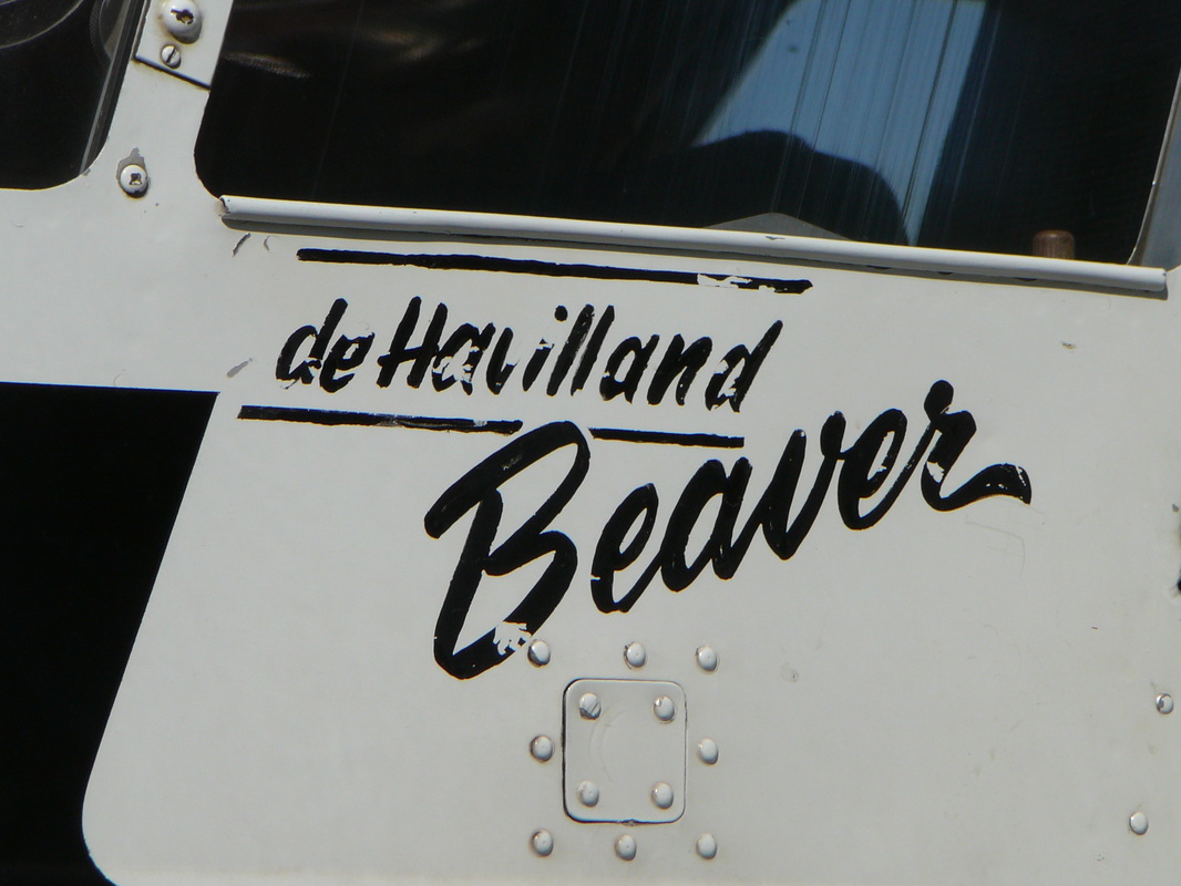
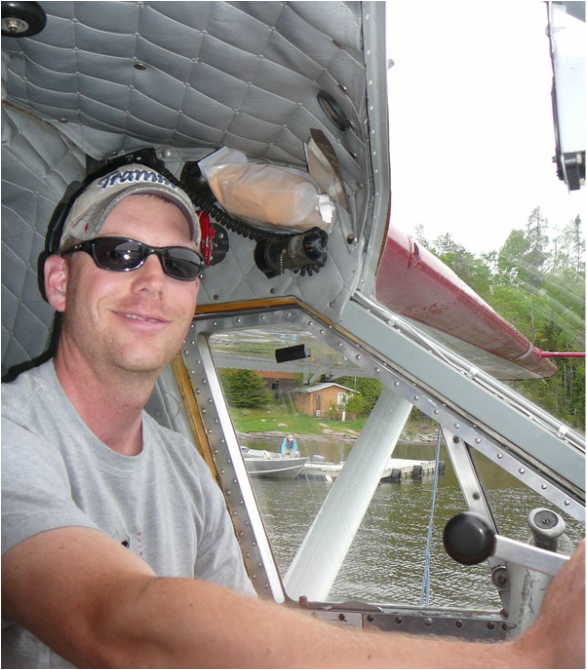
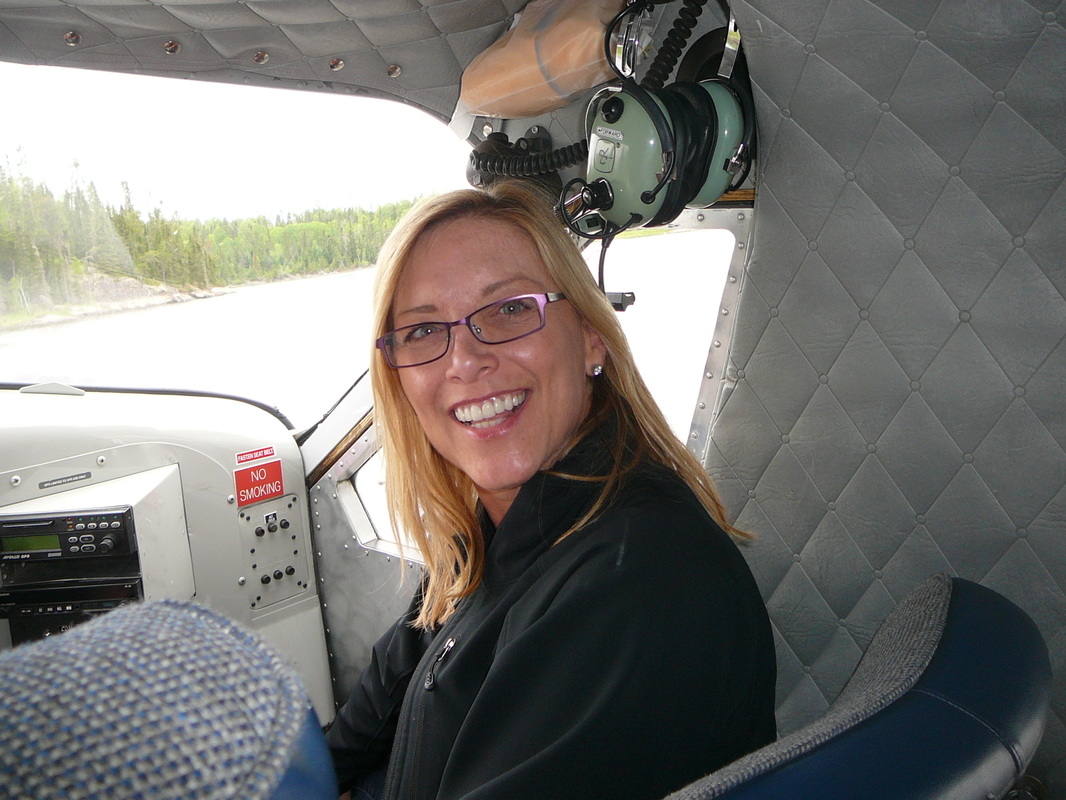
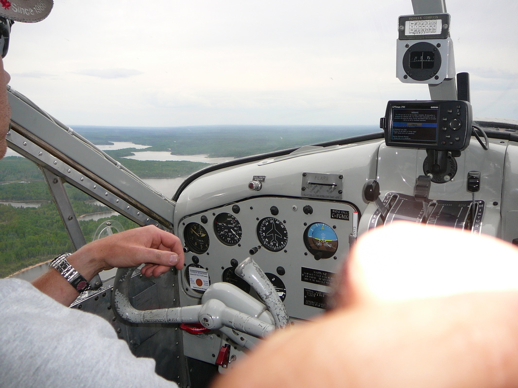
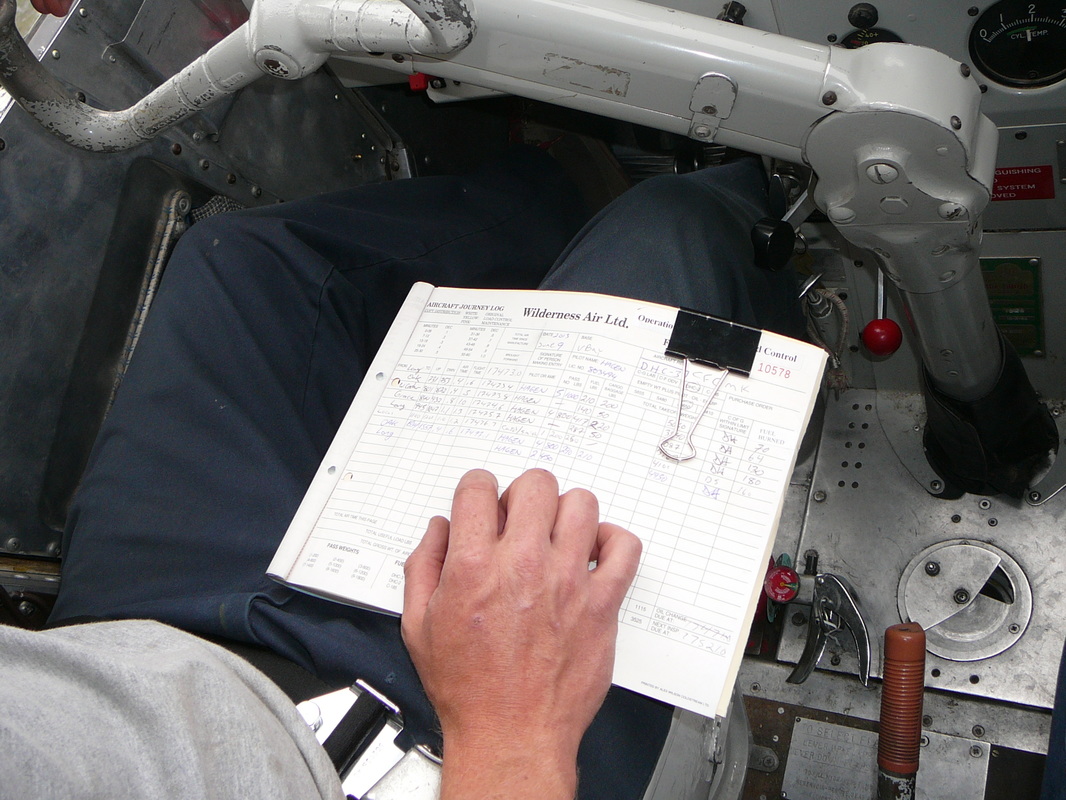
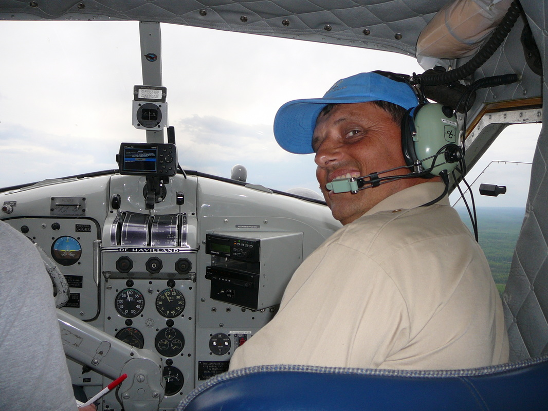
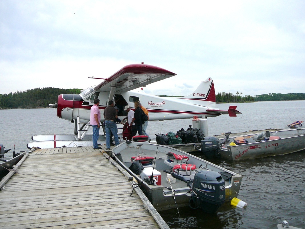
Meet, greet and a flight with Dennis In the Dispatch Office I was introduced to our pilot, Dennis. Our flight to Oak Lake Lodge was arranged for the late in the afternoon. Oak Lake Lodge is arranging an ‘American Plan’ style deal whereby all the necessary equipment, fishing gear, food and fuel are provided. In addition, the services of a guide are included in the package, who takes the group to the best fishing locations while cooking the meals and seeing to the welfare of the clients. Dennis showed us the route on the large area chart in the office. He went on to say that all flying was VFR and that local detailed knowledge of the rivers, lakes and location of each destination is essential. Use of GPS is a great aid to navigate and backed up the knowledge gained by looking through the cockpit windshield. Pilots also had to learn about the vagaries of wind and water conditions and seasonal variations in the weather. Furthermore, in a floatplane like the Beaver there is always plenty of water on which to land in an emergency. Dennis had only two clients for the charter to Oak Lake Lodge. Oak Lake Lodge is located around 30 minutes north-west of Vermilion bay. They both were travelling light as they had booked ’American Plan’. Once the passenger door was closed again, Dennis arrived in the cockpit and courteously welcomed everyone on board and gave a brief safety talk. He then gave me a spare headset so I could listen into the R/T and talk to him on the intercom. After starting the R-985, Dennis signaled to Jon to push the Beaver away from the dock. As ‘Mike-Kilo’ taxied across the water and through a narrow channel into the wider part of Long Lake the engine oil had warmed up about the required 40 degrees Celsius and we were ready to roll! |
|
|
The roar of the Pratt & Whitney R-985
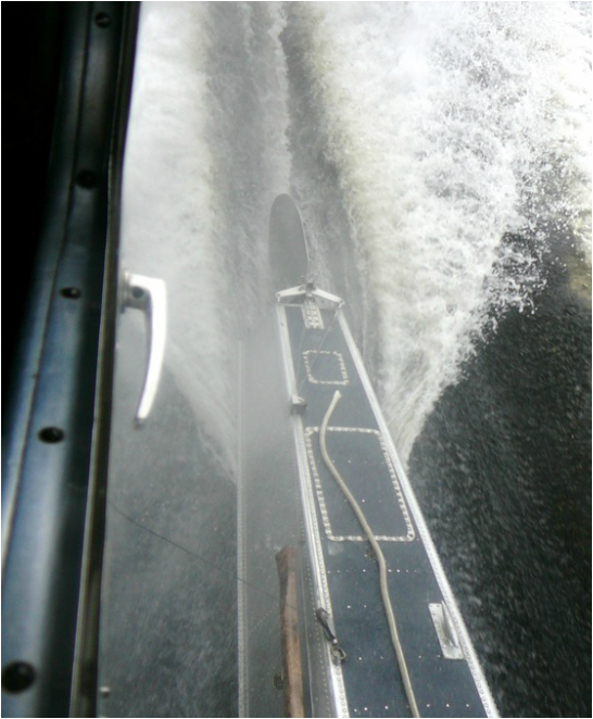
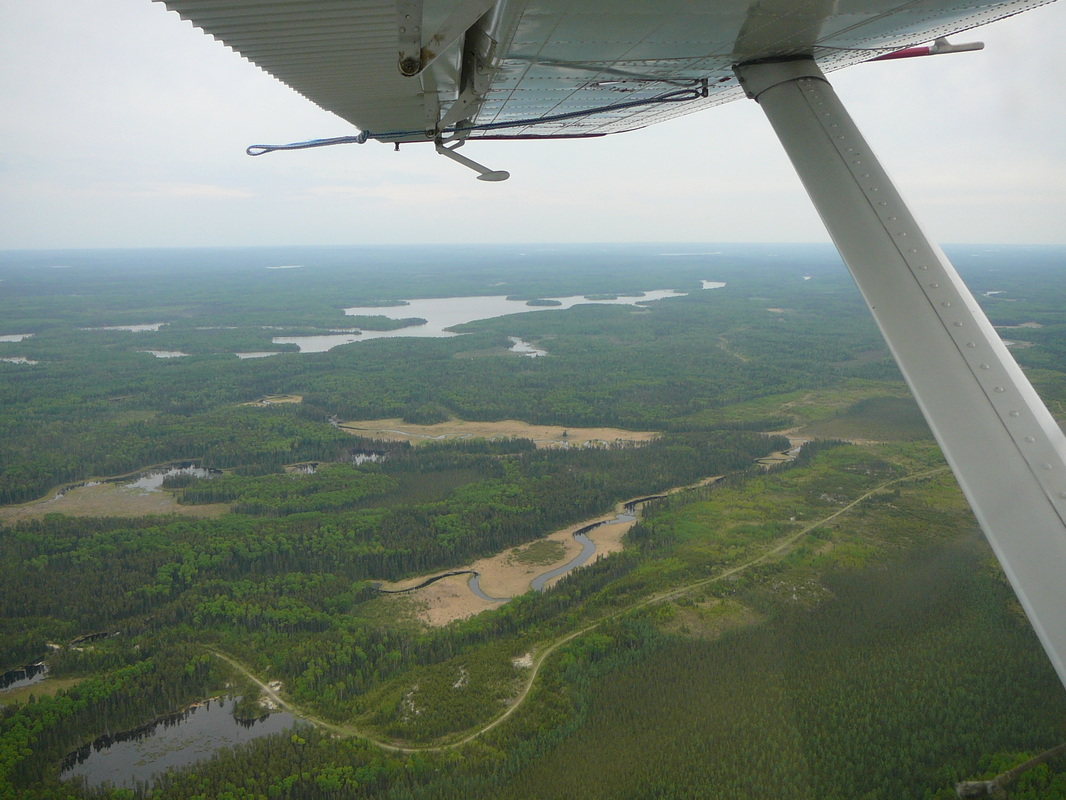
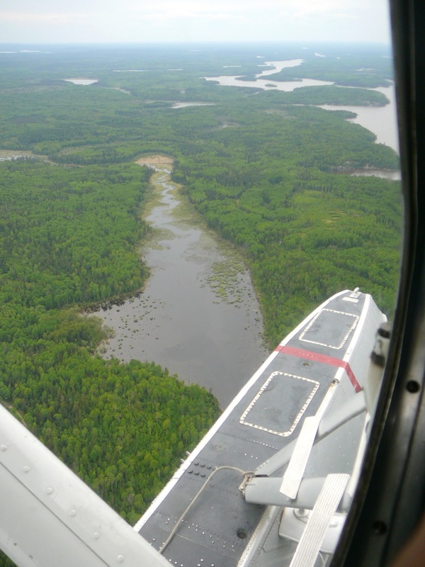
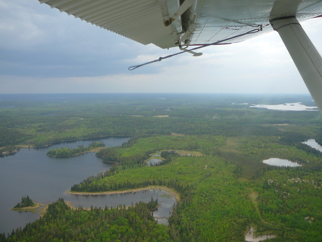
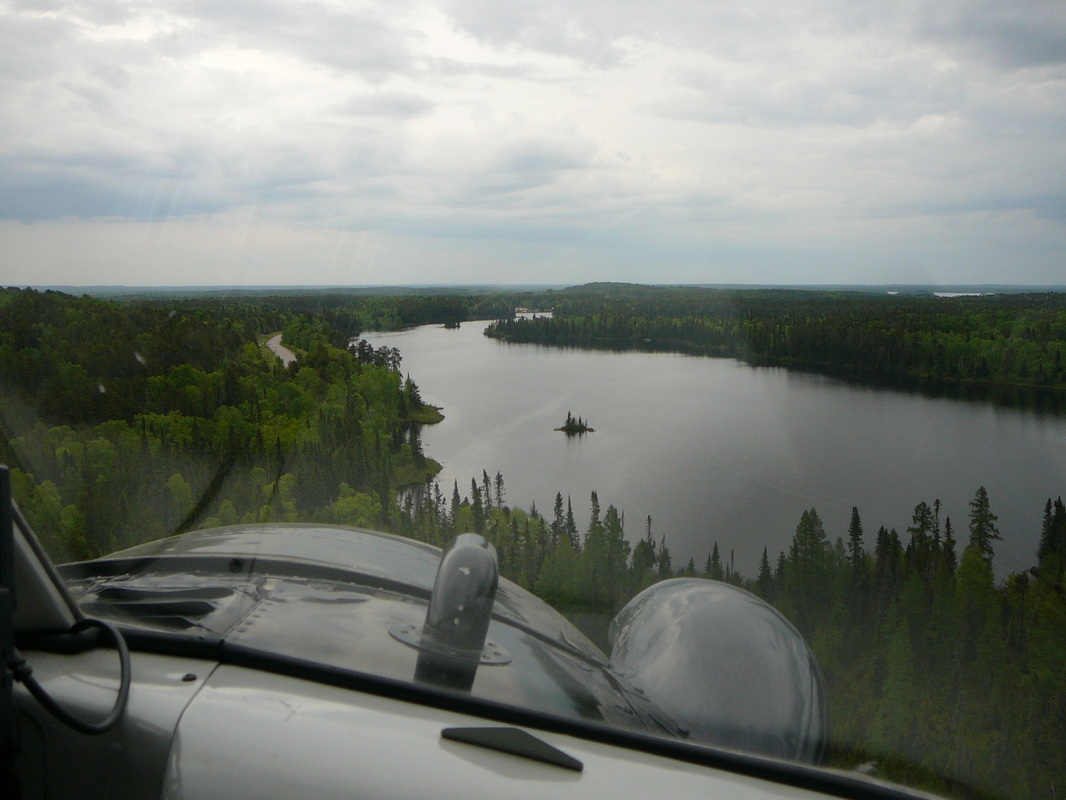
When the floatplane started its take-off run, the roar of the Pratt & Whitney R-985 Wasp radial engine reverberated off the rock outcrops surrounding the lake. The Beaver accelerated on the foaming water, rose on the ‘step’ and with gentle rearward movement on the control column she became airborne. Visibility was good and as we flew overhead the base I could see the piston Otter maneuvering on the water below. There was some chatter on the ATC frequency as we passed the Vermilion Bay airstrip and thereafter unfolded a panorama of picturesque lakes and boreal forest. The handling rope on the wing was flapping in the slipstream as the flight proceeded along the many lakes and rivers. It was smooth ride and far too soon Oak Lake became insight. Before landing on the lake, Dennis did an aerial surveillance of the area checking for obstructions such as floating logs or rocks close to the surface of the water. Wind direction must also be taken into account. Different techniques are required for on-shore winds than would be sued for off-shore winds. Flaps were lowered and the approach to Oak Lake began. |
|
Coffee and muffins
The floats gently brushed the water with a ‘splash’ and the aircraft decelerated. Dennis taxied the Beaver towards the jetty and shut down the engines to let the floatplane gently drift in the water. This is the moment where the judgment of the pilot is essential, if the dock is approached too fast there is the danger of a collision and damage to both aircraft and dock. Too slow and the aircraft will not reach the dock, thereby causing some embarrassment to the pilot! The Beaver came to rest and the mooring ropes were secured to the tie-down points. The staff of the lodge opened the cabin door to allow the passengers to disembark onto the dock. Our flight time had been a mere 35 minutes. Thanks for Dennis for letting me fly right seat! Within half an hour the passenger change was completed and the big radial engine fired up impressively again. One of the lodge staff on the jetty released the mooring rope and off we went. Dennis opened the throttles causing his Beaver accelerated across the water and seconds later we were on our way back to the Wilderness floatplane base. After arrival back at the base, we absorbed the beauty of the setting for a moment longer. Finally, it was time to leave. We thanked the Wilderness Air staff for their kind hospitality, left the dock and made our way to a coffee shop for coffee and muffins. Thanks for Dennis for letting me fly right seat! |
