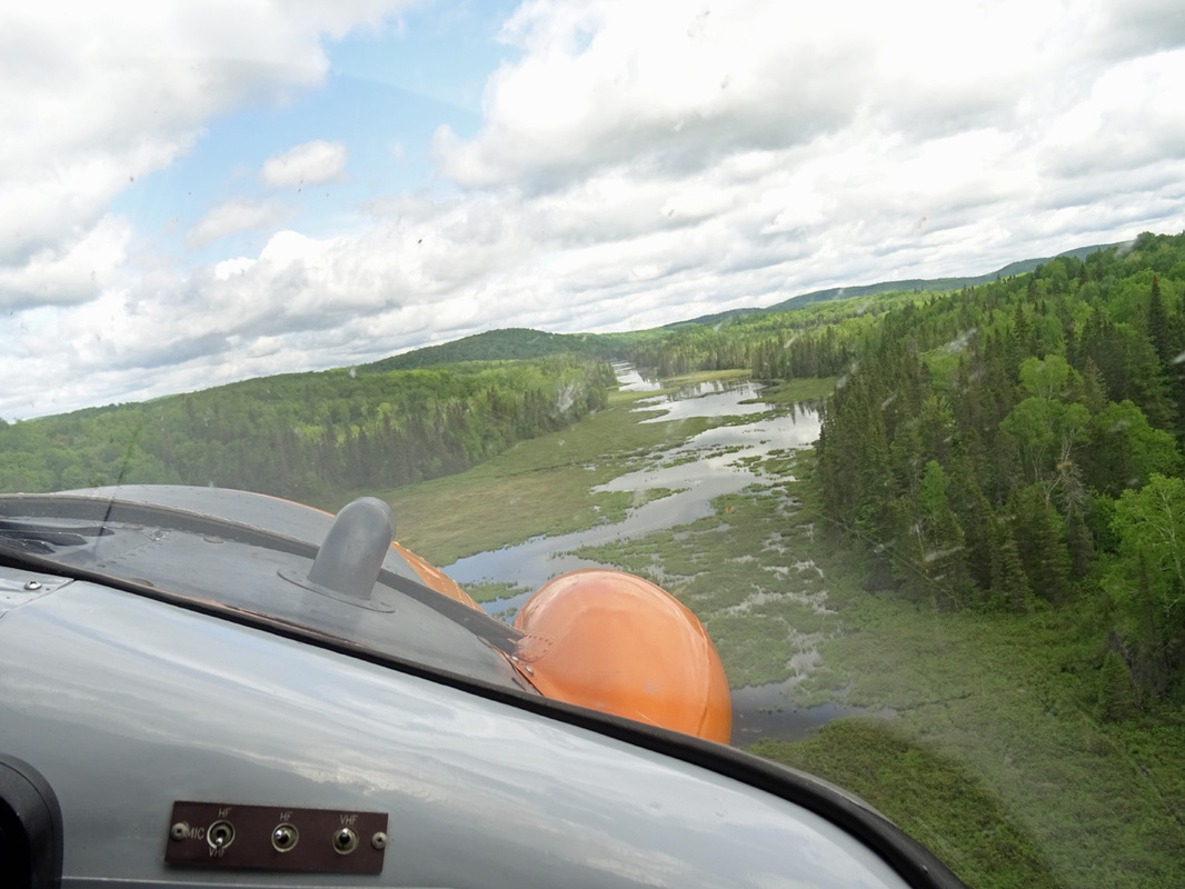
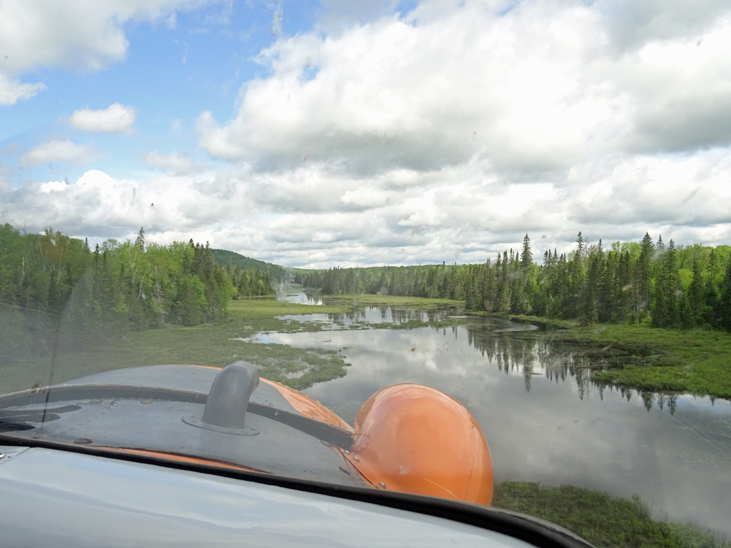
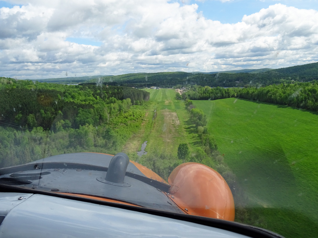
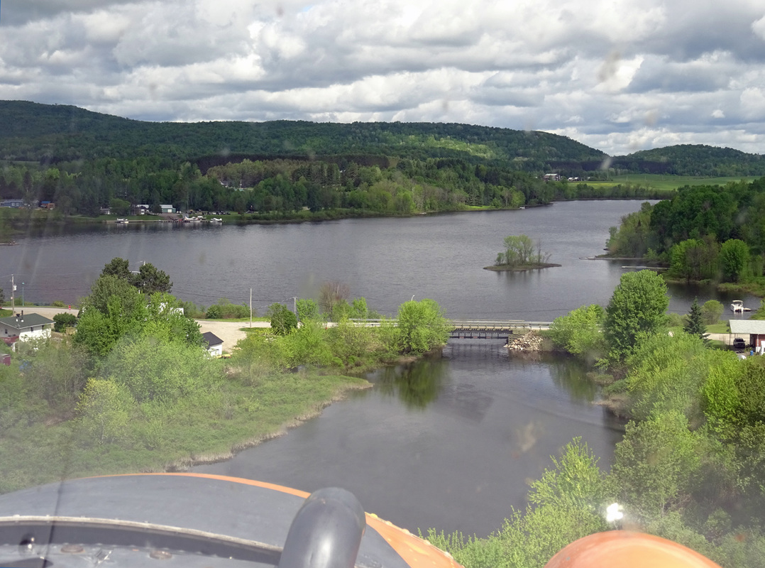
Quebec Bush-planes 2016
The Laurentian Mountains
By Jan Koppen
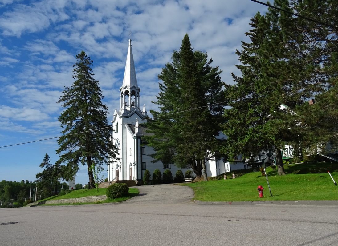
Saint-Veronique
It was a long drive form Lac Sébastien to Sainte-Véronique in the beautifull Laurentides mountains but 'General Lee' performed as expected and I arrived safe at Lac de Tibériade.
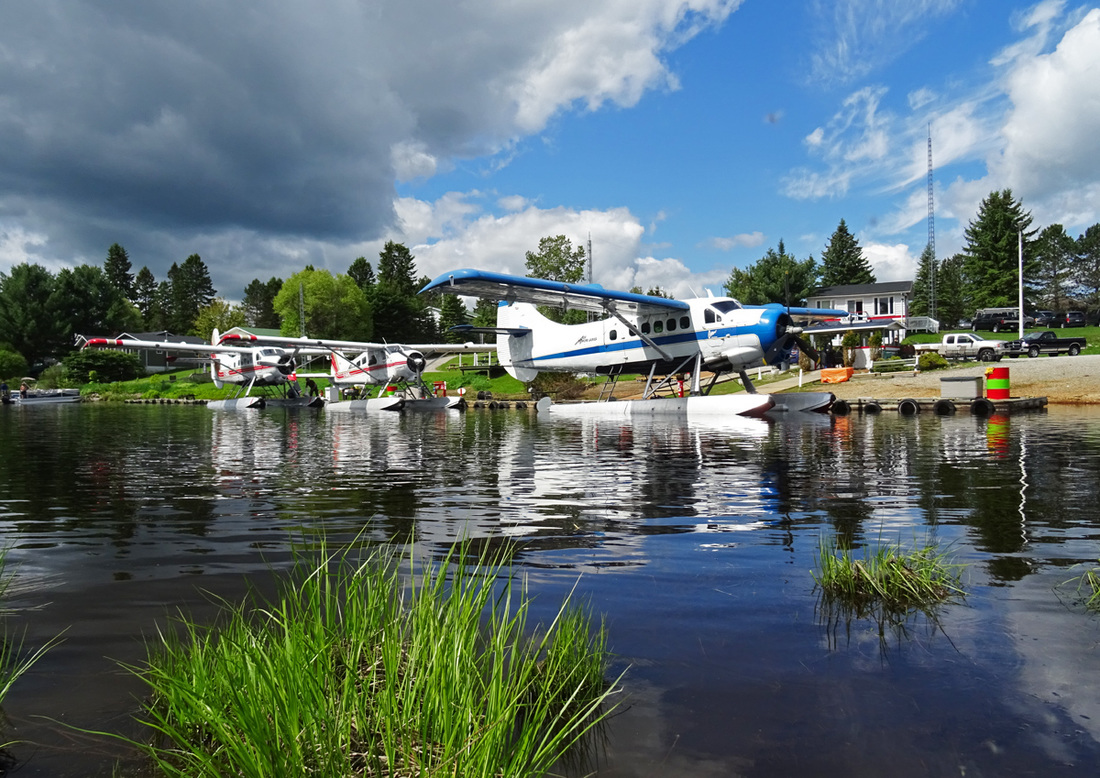
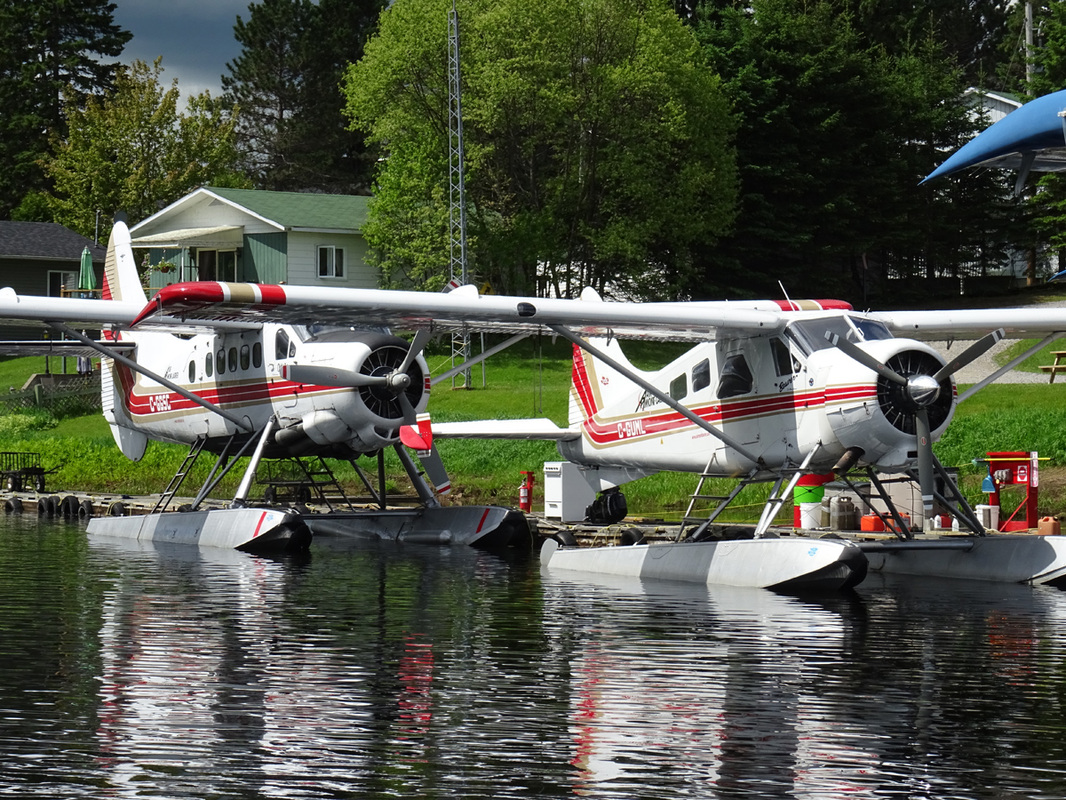
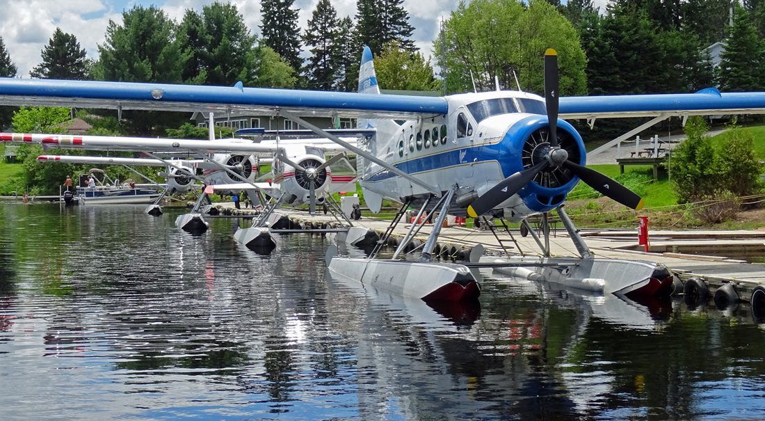
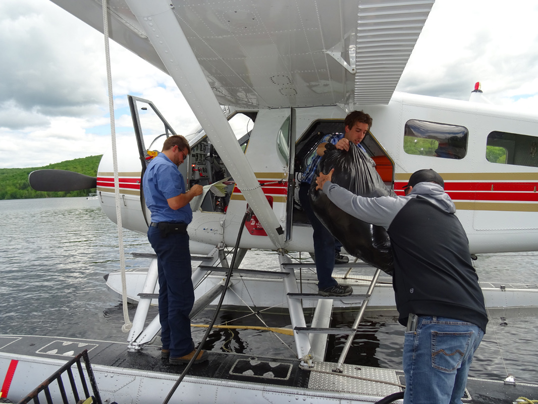
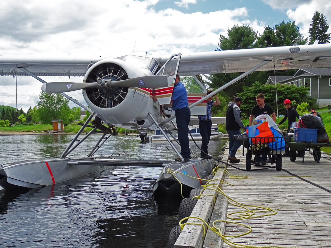
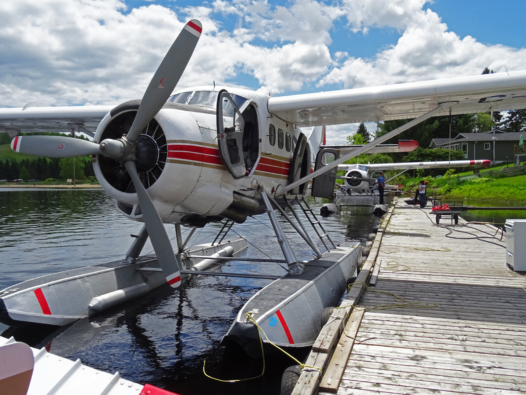
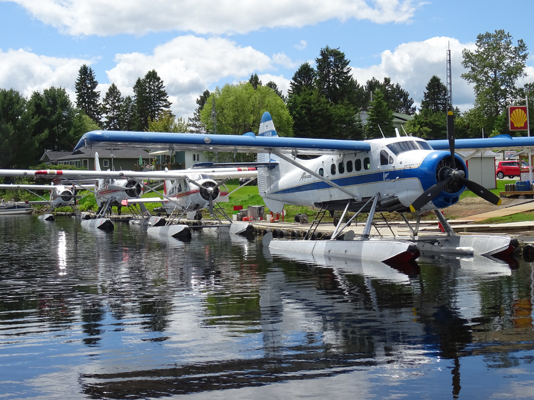
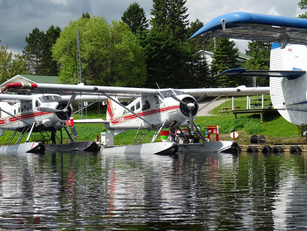
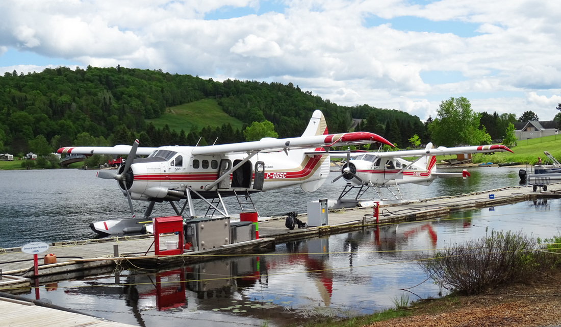
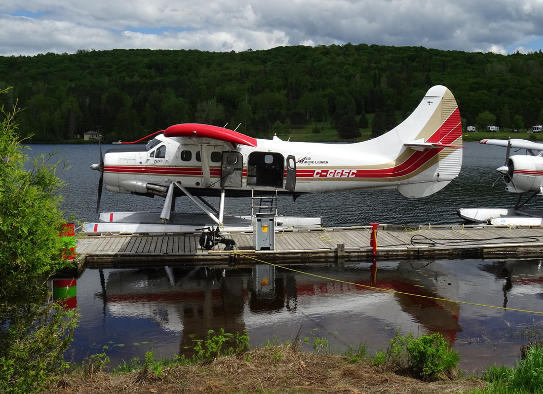
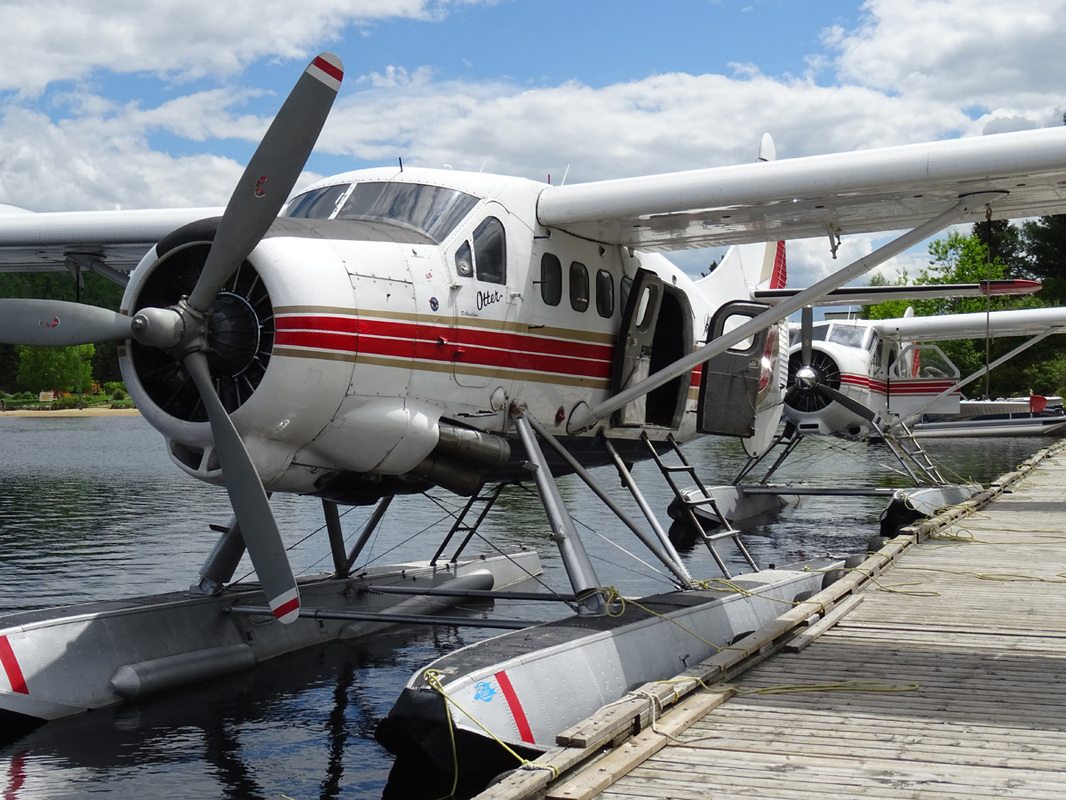
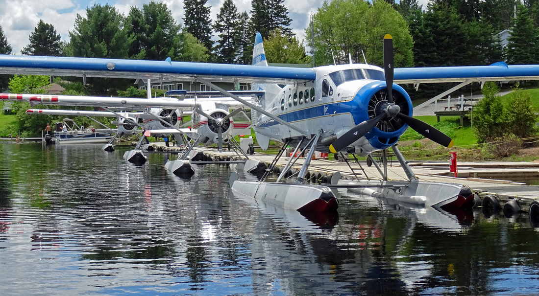
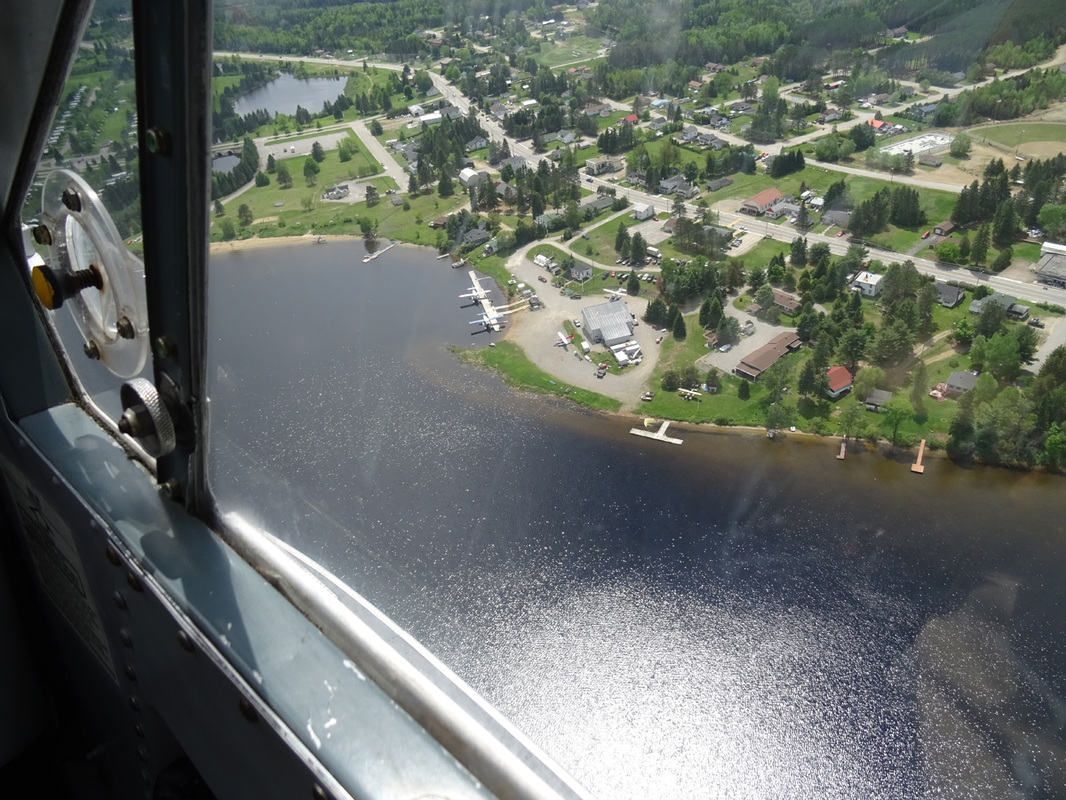
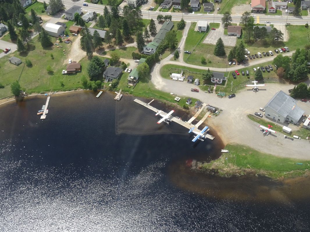
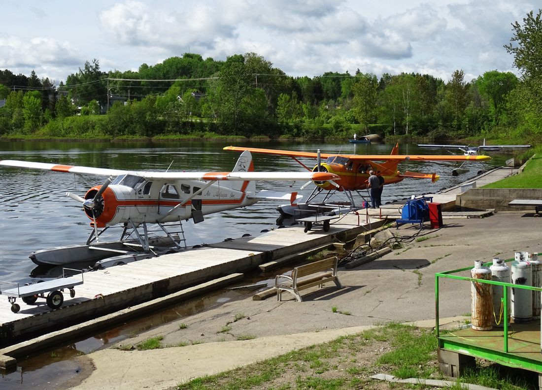
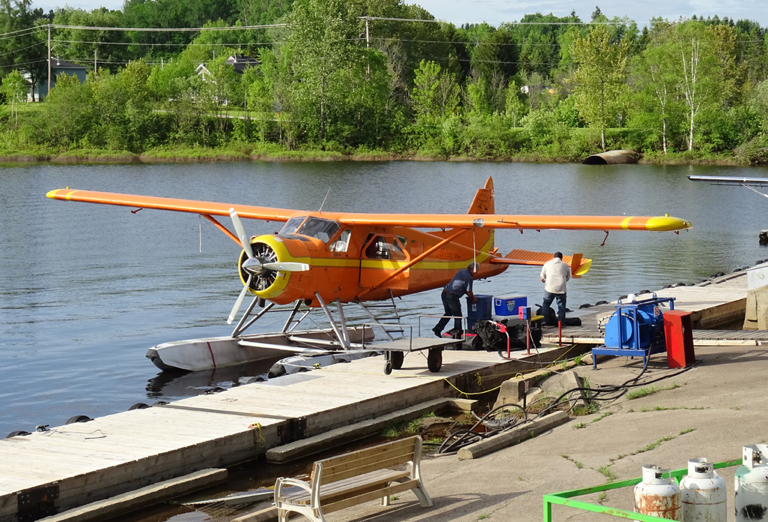
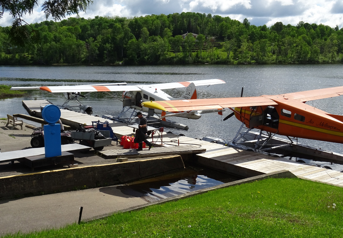
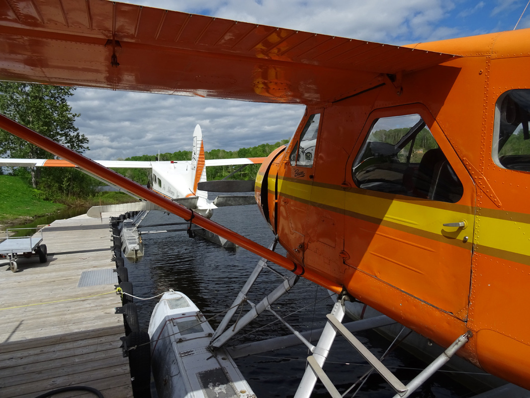
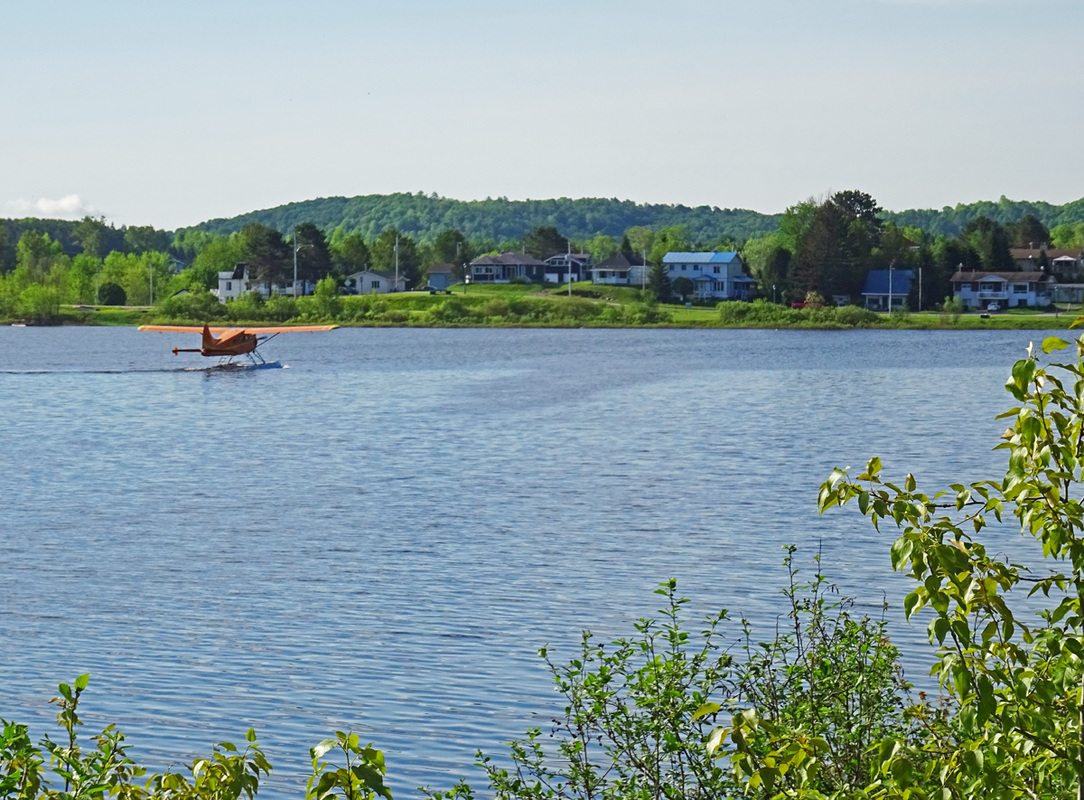
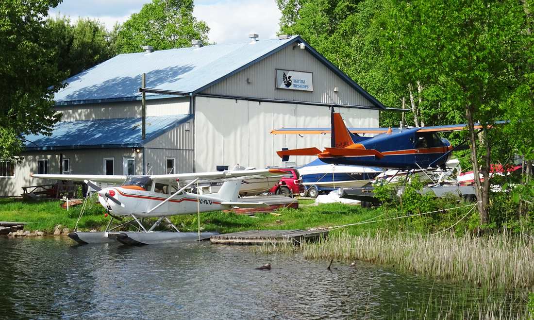
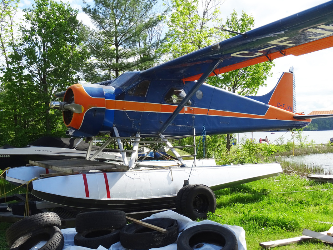
The waterfront scene at Air Mont-Laurier at Lac de Tibériade, Quebec.
|
Air Mont-Laurier is a serious and reliableair transportation company with a small fleet of well maintained DHC-3 Otters, DHC-2 Beavers and one Cessna 185. Air Mont-Laurier is also operating for several fishing and hunting outfitters at Lac du Mâle. Located at the very Northwest end of the Gouin Reservoir, Lac du Mâle is a privileged site for walleye and northern pike fishermen. These outfitters are located in wild territories where only one cabin sits on each lake. One can fish native trout or go bear and moose hunting. This is also an ideal location to enjoy a vacation in nature.
|
|
Watch the show!
Air Mont Laurier DHC-3 Otter C-GGSC perfoming a smooth landing at Lac Tiberaide. Enjoy |
|
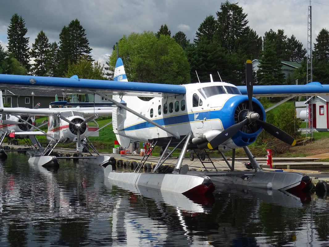
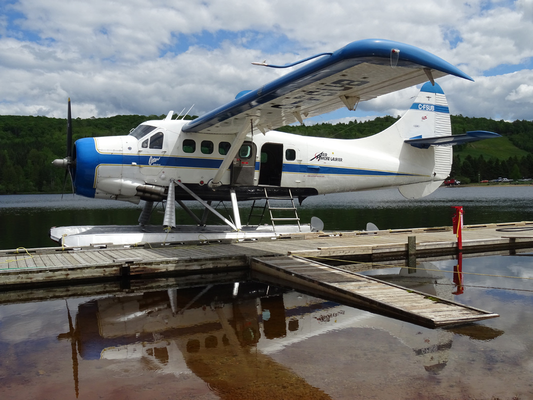
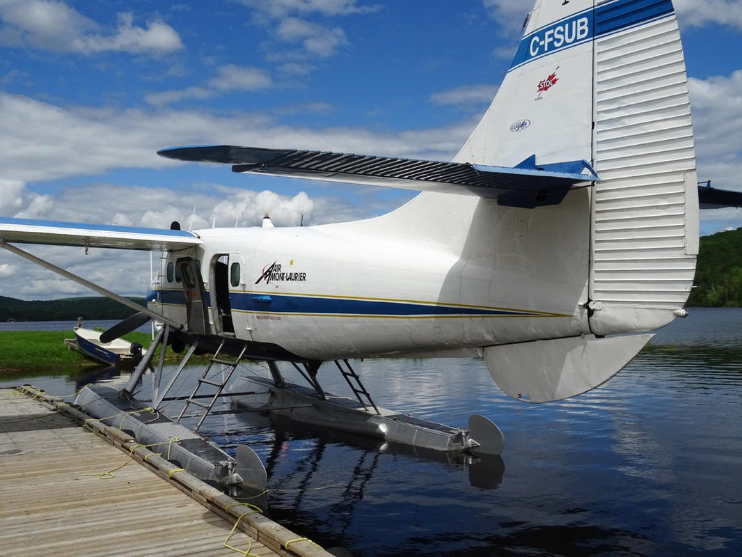
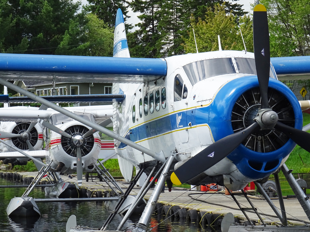
Otter C-FSUB was delivered to the RCAF with serial 3662 on 28th March 1953. Its first assignment was to 408 Squadron at Rockcliffe. Several years later, it joined 111 Communications & Rescue Flight at Winnipeg. The Otter operated out of Winnipeg on wheel-skis during the winter, and on floats from Lac du Bonnet during the summer.
3662 continued in service with 111 Communications & Rescue Flight at Winnipeg until September 1957, when it went to No.6 Repair Depot at Trenton for storage as a reserve aircraft. In October 1964 it was transferred to Saskatoon and continued in storage awaiting disposal. After military service she returned to DHC in 1965, who converted it to civilian configuration.
From then on the Otter became a hard working member of many Canadian bush-plane operators, hauling fuel, diamond drills and supplies for mining and exploration camps. Her operators were Coast Range Airways Ltd of Atlin, BC, to whom it was registered on 7th February 1966 as CF-SUB, Trans North Turbo Air Ltd of Whitehorse, Yukon, Great Northern Airways Ltd of Calgary, Trans North Turbo Air (1971) Ltd., Tyee Airways Ltd of Sechelt, BC. and Air North Charter & Training Ltd, After four years of service in the Yukon with Air North, SUB returned to the Vancouver area when it was purchased by Harbour Air Ltd. It arrived in Vancouver in October 1984 on delivery.
It was overhauled and repainted over the winter and it flew with them for that summer, before heading north up the BC coast to Prince Rupert, where it was registered to North Coast Air Services Ltd in November 1985. It joined their fleet of four Beavers, a Fairchild Husky and a Grumman Mallard and flew for North Coast for nearly two years.
Having served all of its commercial existence thus far in Western Canada, it then moved eastwards, where its next operator was Kelner Airways of Pickle Lake, Ontario to whom it was registered during June 1987. It flew that summer out of Pickle Lake and then moved further east, when it was acquired by Cargair Ltee of Quebec, to whom it was registered in October 1987.
Since then, SUB has served with Cargair, based at St.Michel-des-Saints during the summer months on floats, being put into storage each winter. The Otter is used to fly tourists, hunters and fishermen into the beautiful wilderness areas of Quebec. It also supports exploration camps in the James Bay area. During the caribou hunting season of August/September each year, the Otter flies out of the LG-4 base on the La Grande river, flying the hunters to the James Bay region in search of their prey, before returning to St.Michel-des-Saints for winter storage. The Otter has been operated by Cargair Ltee from its base at St.Micheldes- Saints, Quebec for twenty years, since 1987.
In 2007 the bush aircraft division of Cargair, including the Otter, was purchased by Air Mont Laurier (1985) Inc of Ste.Veronique, Quebec to whom C-FSUB was registered in April 2007. Air Mont Laurier also operate Otter C-GGSC (366), both Otters still with their original R-1340 engines.
Info credit: DHC-3 website/ Karl E Hayes.
Info credit: DHC-3 website/ Karl E Hayes.
|
Description of aircraft
The DHC-3 Otter airplane is an all-metal, high wing monoplane powered by a single Pratt and Whitney Wasp engine driving a Hamilton Standard constant speed propeller. The aircraft has been designed to carry a pilot and from six to eleven passengers. Through partitions the aircraft is divided into a cockpit, a cabin and a baggage compartment. The general over-all dimensions of the airplane are; length 41 feet, 10 inches, wing spans 58 feet and height 12feet, 6 inches. The maximum gross weight of the aircraft is 7967 pound in seaplane configuration. The oil tank, which is of 9 Imp. gal. (40,5 liters) capacity is located under the cockpit floor. Servicing of the oil tank is done through a filler neck on the left side of the fuselage. The oil cooler with an integral surge relief valve and a thermostatic by-pass valve is located behind the firewall and has its own air-flow system. Fuel is contained in three flexible bag-type tanks beneath the forward portion fo the cabin floor. The tanks are buttoned with fasteners to the underside of the floor, to stringers and the skin of the fuselage. The tank capacity is as follows; front tank 51 Imp. Gal (233 liters), center 85 Imp. Gal (389 liters) and the rear tank 42 Imp. Gal. (192 liters). The center tank consists of two interconnected cells. Each of the three tanks is used separately, the fuel flow to the engine being controlled by the fuel selector valve. An electrically-operated booster pump ensures that an adequate fuel flow is maintained in the event of failure of the engine driven pump. |
|
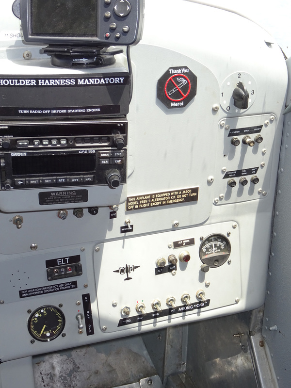
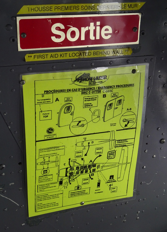
The ELT (acronym of Emergency Locator transmitter) is a device which send a message in case of aircraft crash. That message contains info about aircraft model, owner and approximate coordinates of the crashed plane, and it is made to request SAR (Search and Rescue) services.
Many aircraft ELT have two basic ways to work: In a crash (The ELT will be activated automatically when hitting ground) and by pilot request (In case of emergency, the pilot may press the "armed" button in the remote control to send a emergency declaration message). In both ways, the device will send a message containing relevant information: · Aircraft model · Callsign · GPS Coordinates · SAR service request |
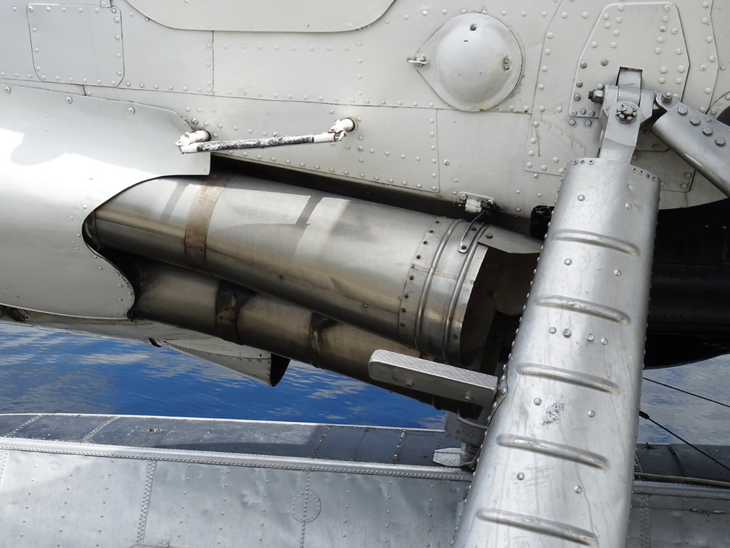
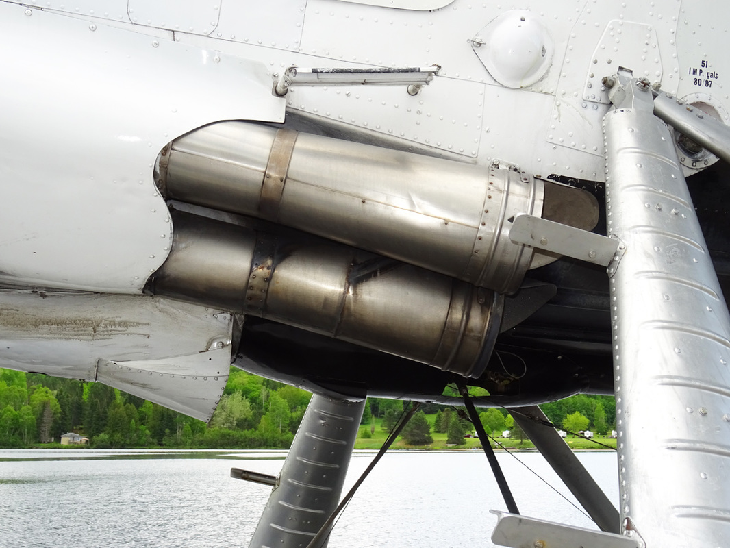
The two exhaust augmentor tubes on both sides of the fuselage, just below the cockpit door, are a special design feature of the aircraft. In these four exhaust augmentor tubes, the exhaust gases produce suction strong enough to pull cooling air around the engine and from behind the engine accessories compartment while at the same time providing a measurable amount of thrust in cruising flight. The engine is thus effectively cooled during steep climbs when the forward air speed is low and engine output near its maximum.
(DHC-3) That massive rudder!
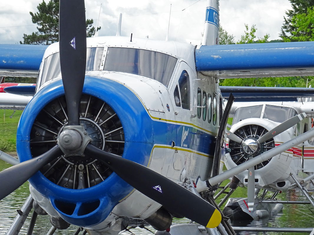
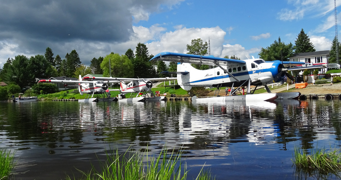
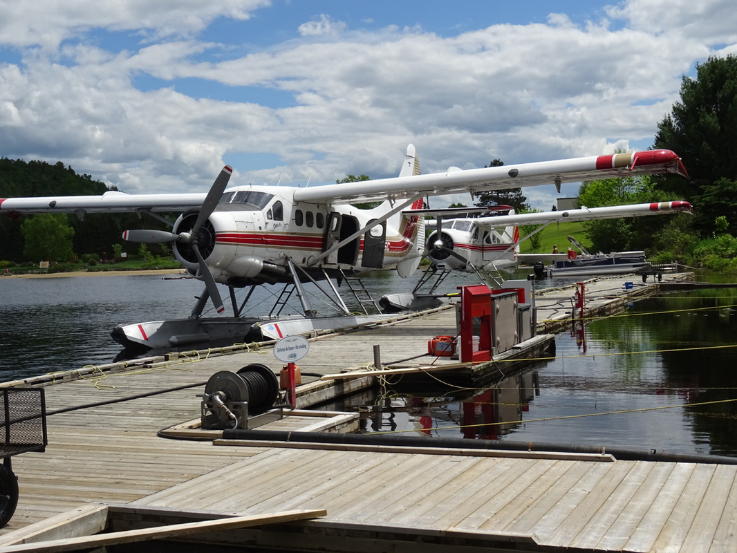
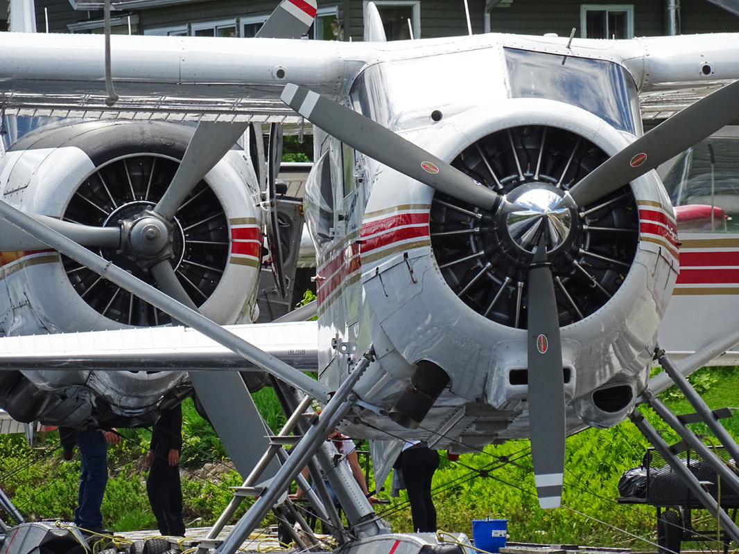
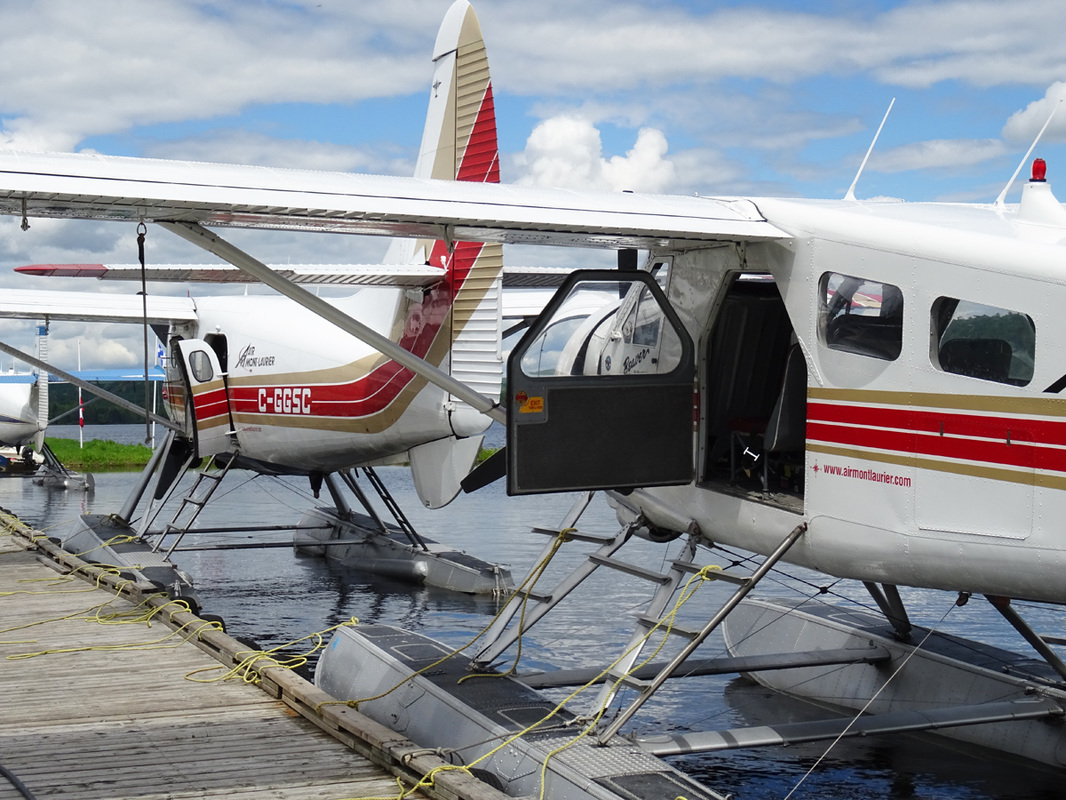
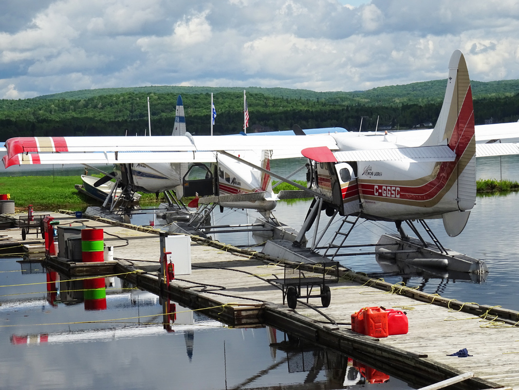
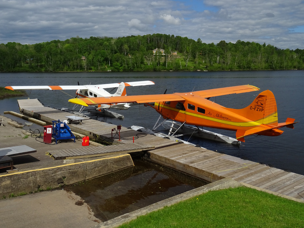
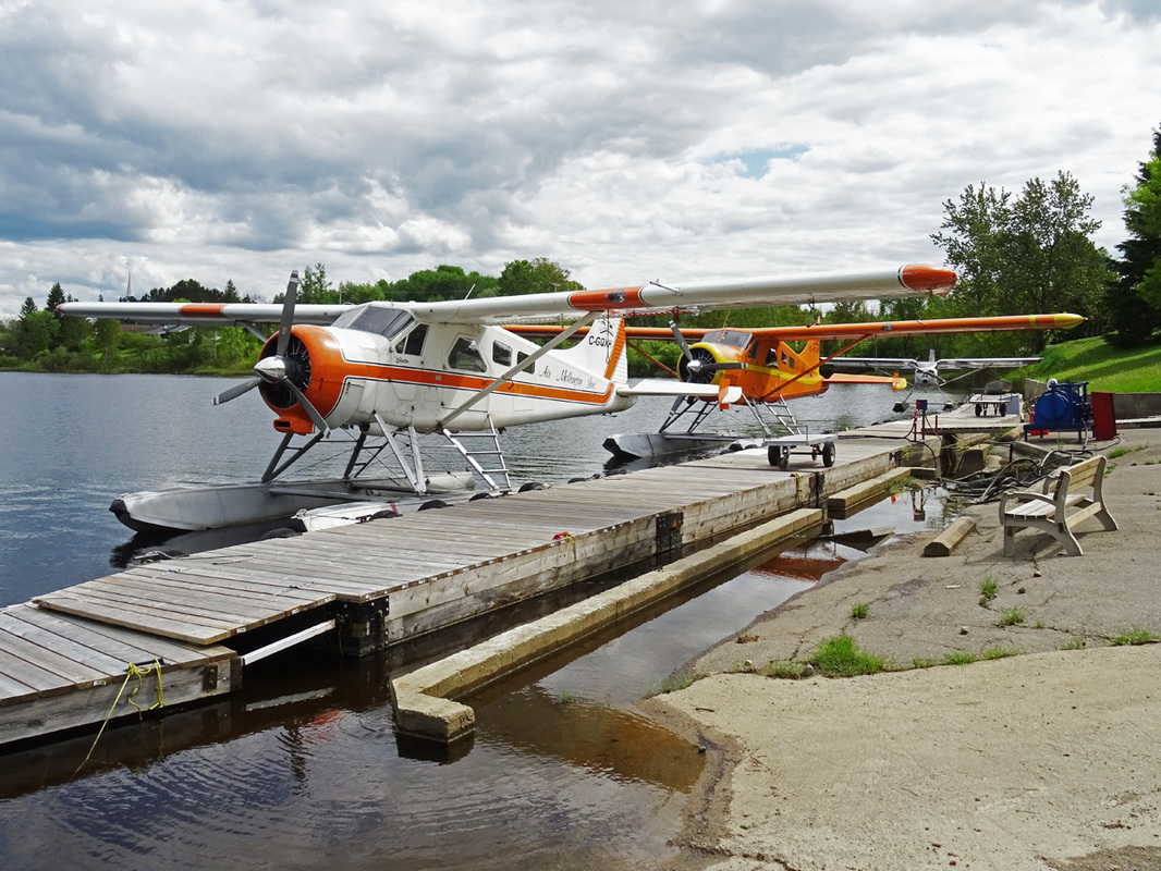
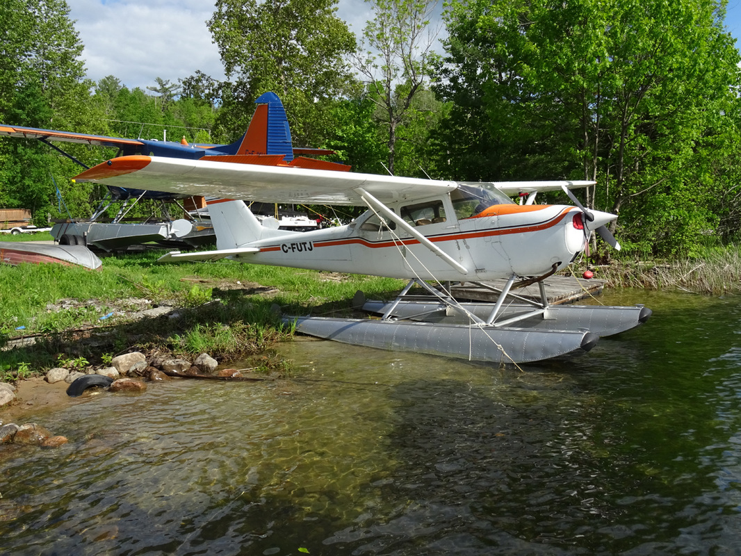
Two Otters and two Beavers bush planes rest in the springtime sun at Lac Tiberiade. Epic scene, incredible experience.
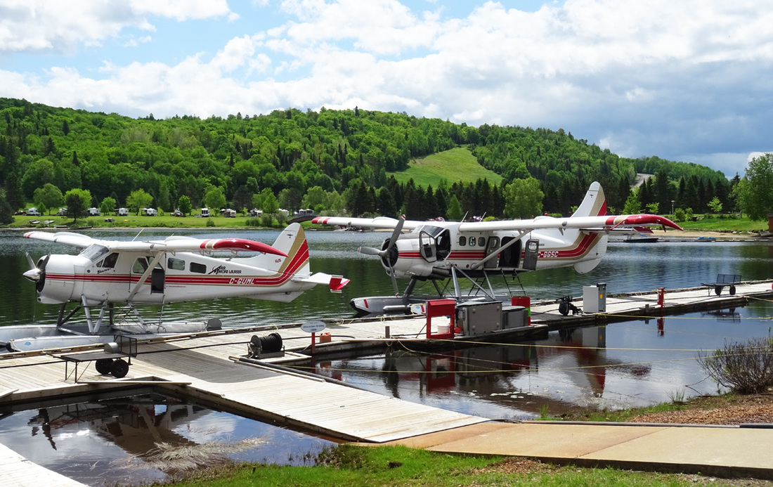
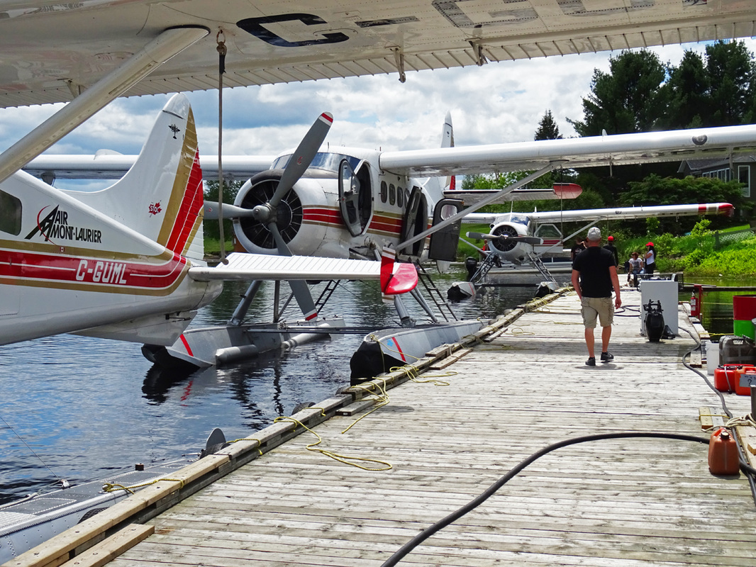
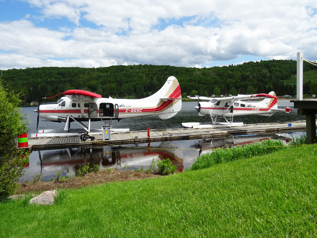
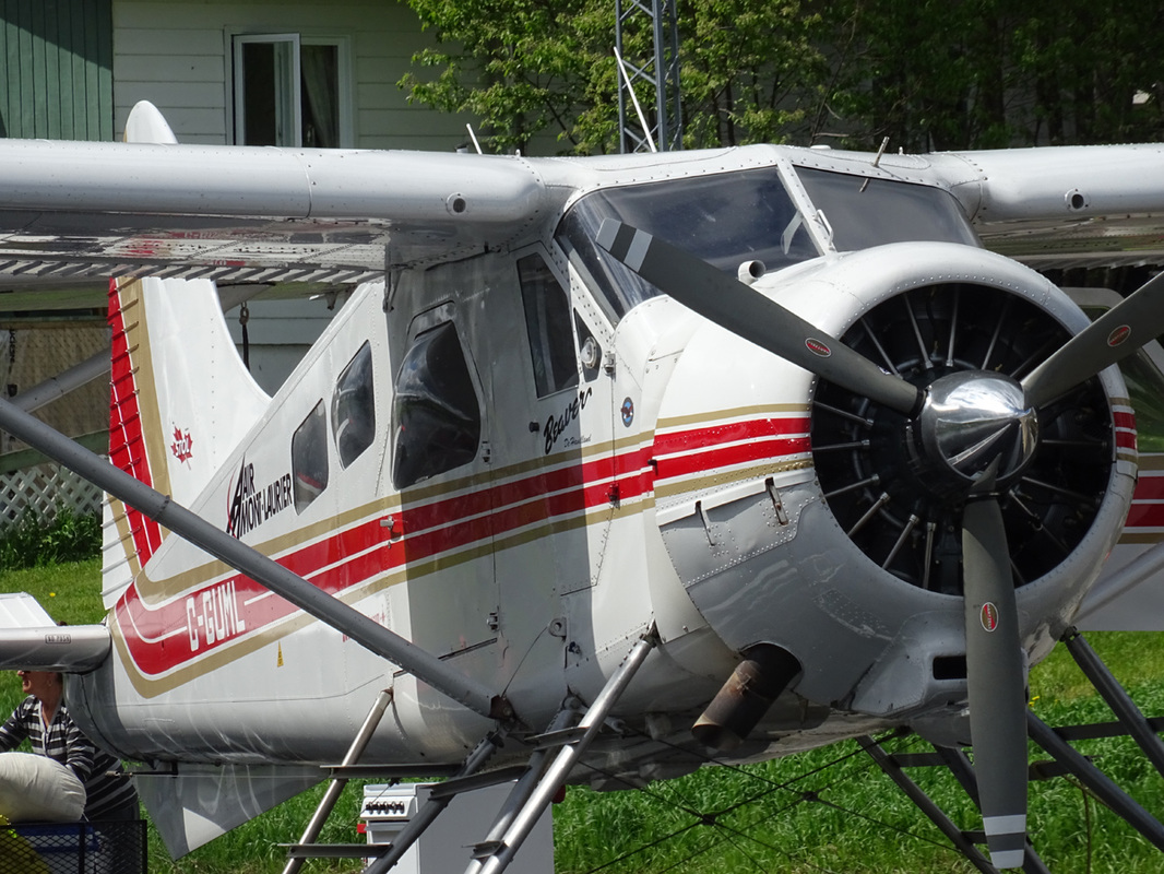
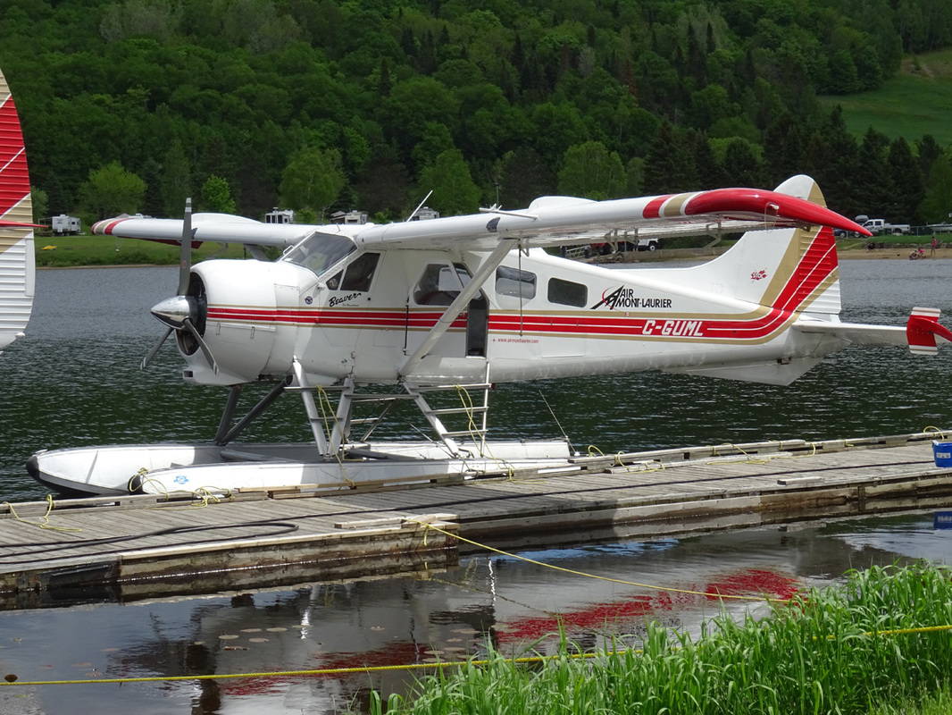
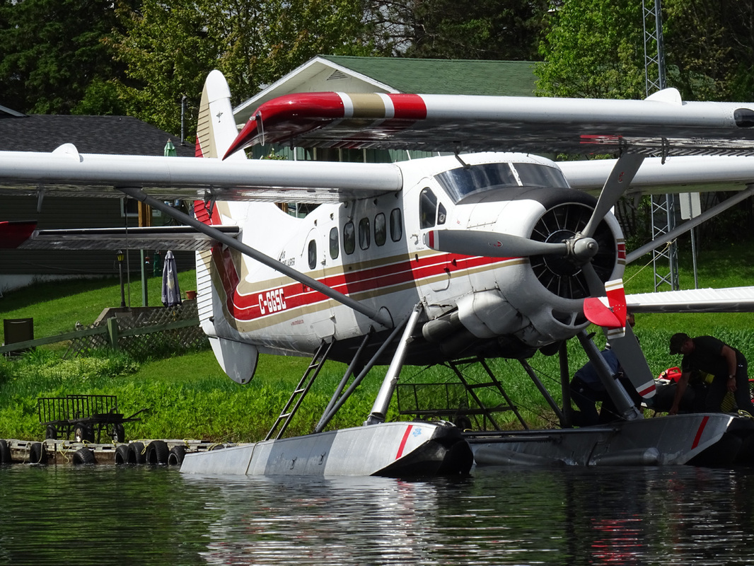
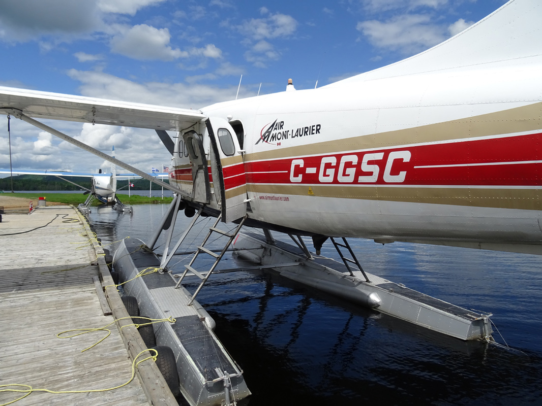
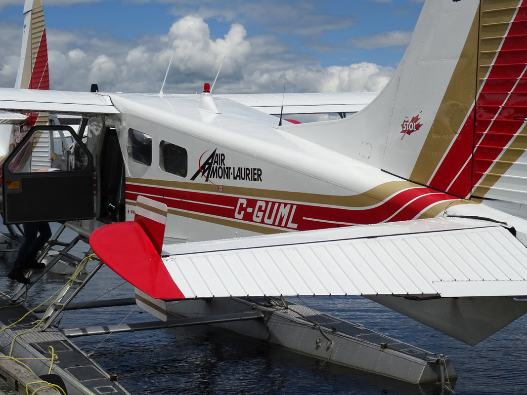
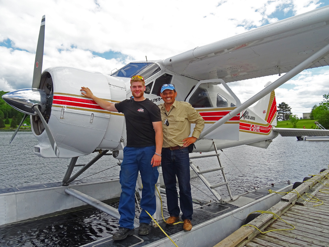
Beaver C-GUML and Otter C-GGSC sits at their dock on Lake Tiberiade awaiting their next assingment.
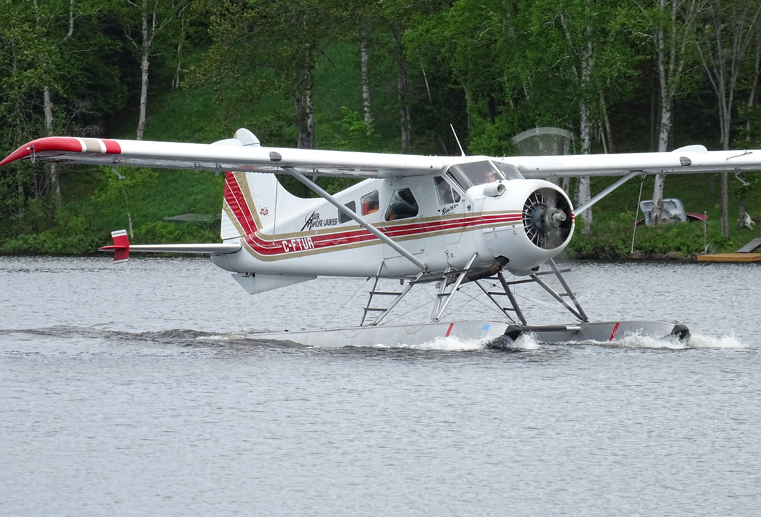
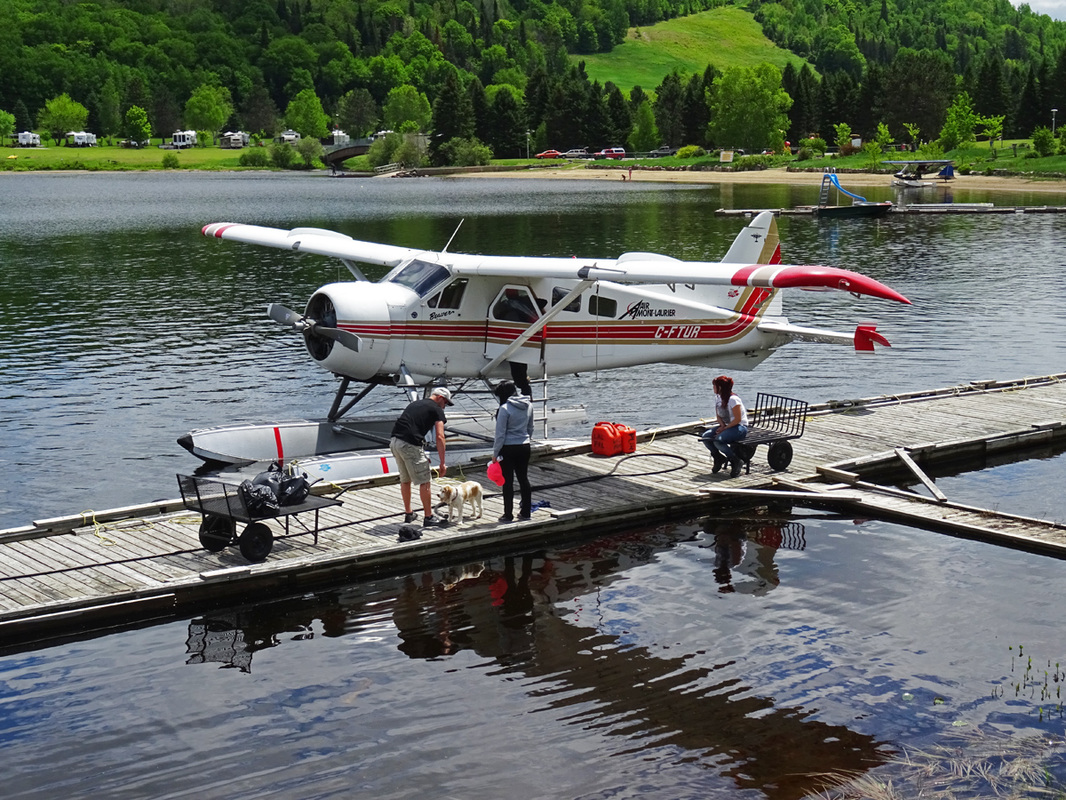
C-FTUR is seen here taxiing in from an outpost camp. Air Mont-Laurier uses C-FTUR to service its lodge and numerous northern lakes.
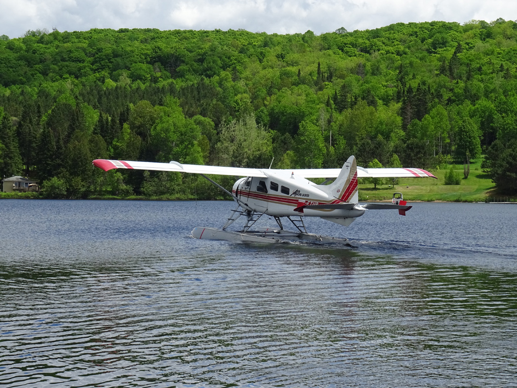
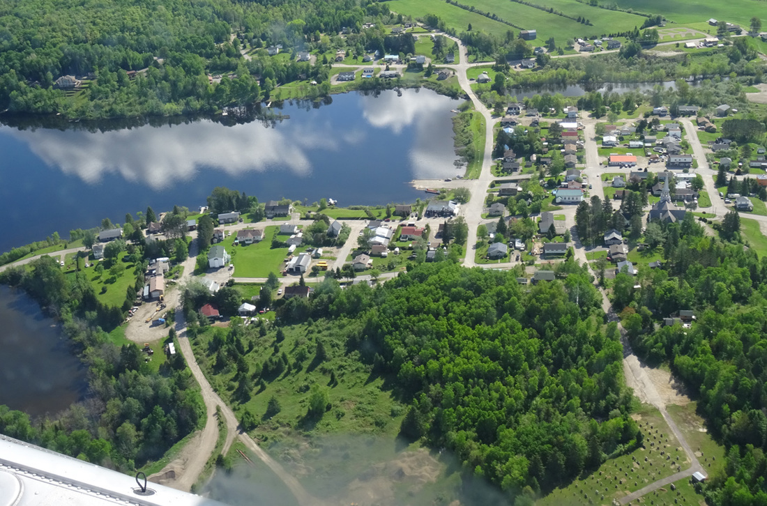
C-FTUR coasts to the dock on Lake Tiberiade at St. Veronique. The community of St. Veronique, located in the middle of the Laurentian Mountains, is on Highway 117, between Mont -Tremblant and Mont-Laurier.
|
Watch the show!
DeHavailland, 1963 built DHC-2 Beaver C-FTUR, approach, landing and docking at Lac Tiberiade. Enjoy |
|
C-FTUR. The history of this DHC-2 Beaver reads as follows; - Delivered in 1963 to the Rodair Inc. as CF-TUR. During the mid ‘70s she became part of the famous Laurentian Air Services. She served several other Canadian bush plane operators before Air Mont-Laurier (1985) of Ste Véronique, Quebec, purchased it in 1996 and is still the present owner.
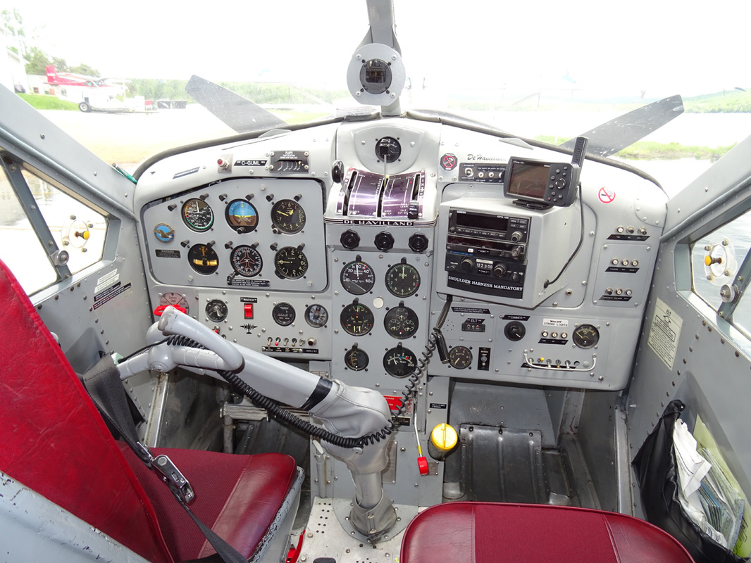
The pilot’s seat is simultaneously adjustable fore-and-aft and for height by means of a screw jack on the front of the seat; a lap type safety belt is provided. The seat cushion has grab-lines and may be used as a life-preserver when abandoning the aircraft in or over water. A first aid kit is located on the back of the pilot’s seat.
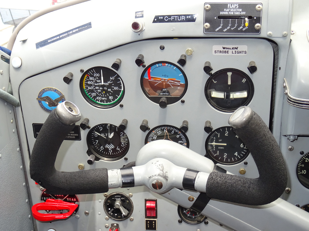
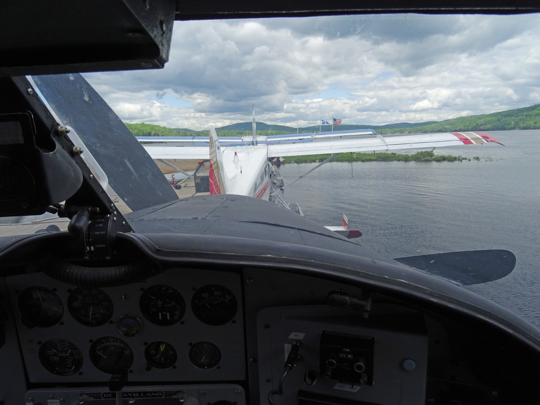
A wing flaps position indicator is situated above the flight instrument panel. It is marked FULL FLAP, LANDING, TAKE-OFF, CLIMB and CRUISE. FULL FLAP is only required for emergency landing in very restricted areas.
|
Description of the De Havilland DHC-2 Beaver
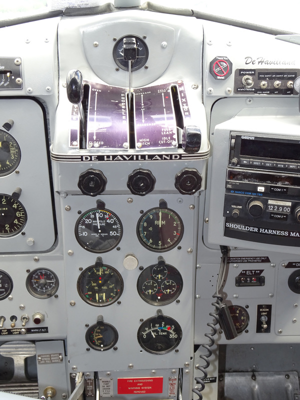
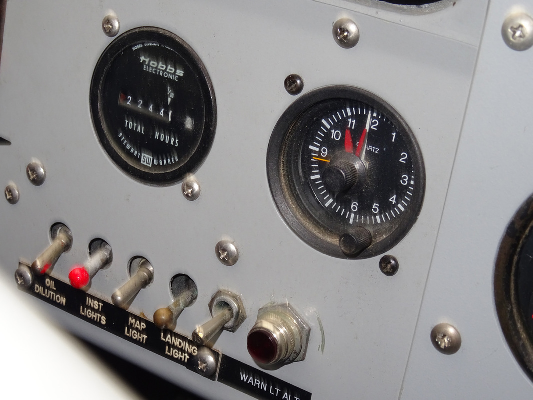
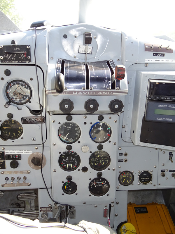
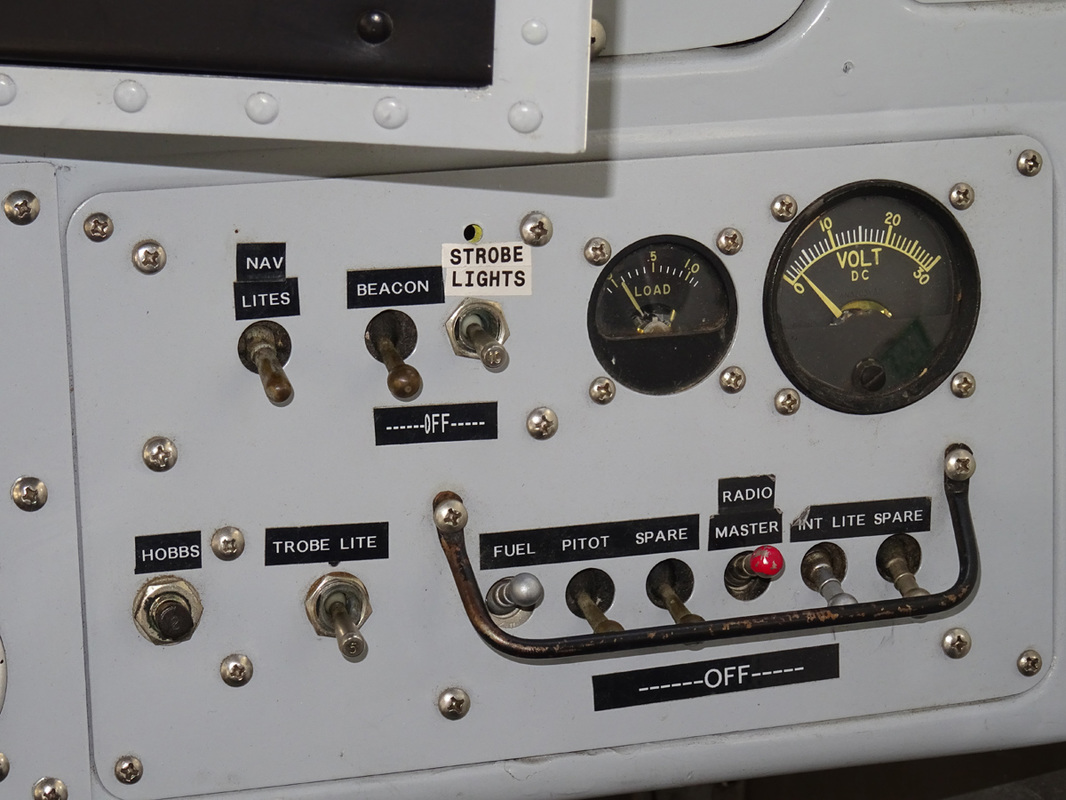
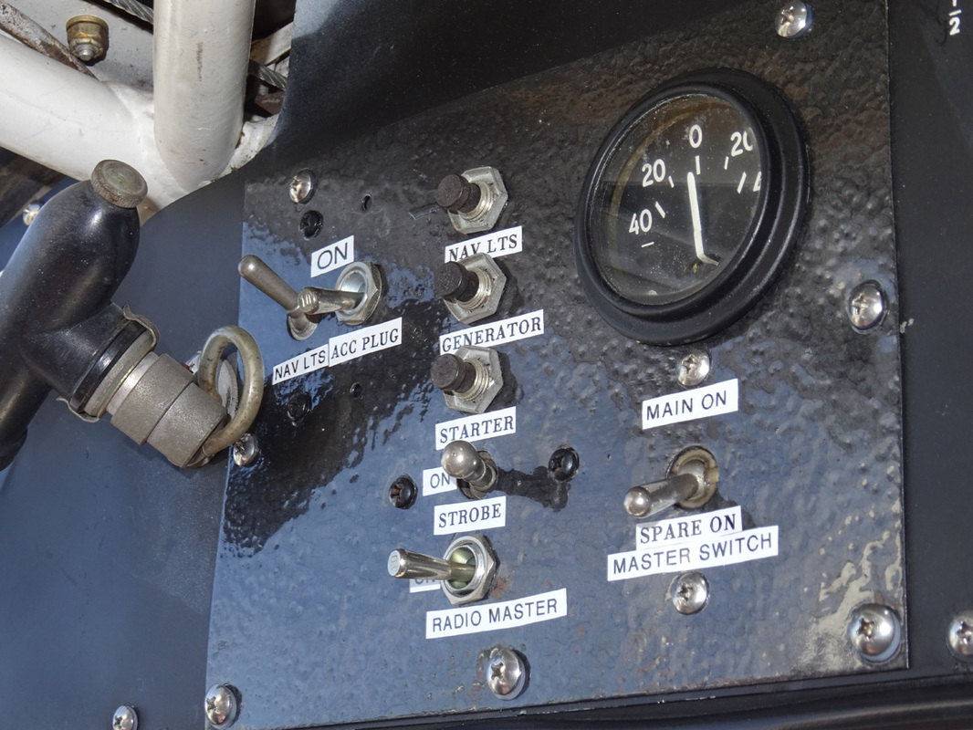
as describe in the Flight Manual of 1957 The DHC-2 Beaver aircraft is an all-metal high-wing monoplane, designed to carry a pilot and seven passengers. The aircraft is powered by a Pratt & Whitney ‘Wasp Junior’ model R-985SB3 nine-cylinder single-row radial engine, rated at 400 BHP at 5,000 ft altitude. The engine drives a Hamilton-Standard constant-speed propeller; crankshaft and propeller rotation being clockwise. Propeller diameter measures 8 ft. 6 in. The engine control quadrants are located at the top of the pedestal. Friction control knobs, one below each control lever, increase lever friction when rotated clockwise. The throttle lever movers in a quadrant marked OPEN and CLOSED. The lever is connected to the throttle valve by means of pus-rods and torque-tube linkage. The mixture lever moves in a quadrant marked as follows: AUTO LEAN – AUTO RICH – FULL RICH – FULL LEAN – IDLE CUF-OFF. The lever is connected to the carburetor by means of push-rods and torque-tube linkage. Electrical DC energy is supplied by a 50 amp 28-30 volt generator in conjunction with a 24 volt 17 amp/hr. battery. The generator output is regulated by a carbon pile voltage regulator. A reverse-current relay is used to protect the generator when is not charging. The battery is stowed in a compartment on the left side of the fuselage, aft of the cabin door and is accessible through a hinged panel on the outside of the aircraft. Nowadays, many Beavers have battery forward modification which has a positive outcome on the CG of the aircraft. The following equipment and controls are operated by the electrical system: Starter, Oil dilution system, Booster pump (if installed), Engine indicators, Fuel contents gauge, Interior lights, Navigation lights, Landing light, Anchor lights (seaplane), Fuel pressure warning light, Electronic equipment, Pitot head heater and Fire warning system. The generator field switch, located on the electrical switch panel, is of the single-pole, single throw type. The battery master switch is located in the left-hand upper corner of the flight instrument mounting panel. It is of the double pole, single-throw type and interrupts the battery output to the electrical system. A volt-ammeter, located in the electrical switch panel, indicates the amperage of the generator supply. The voltage of the generator supply is indicated when charging by pressing the stud at the lower left of the instrument. When the generator is not operating, the battery voltage only will be indicated. |
|
|
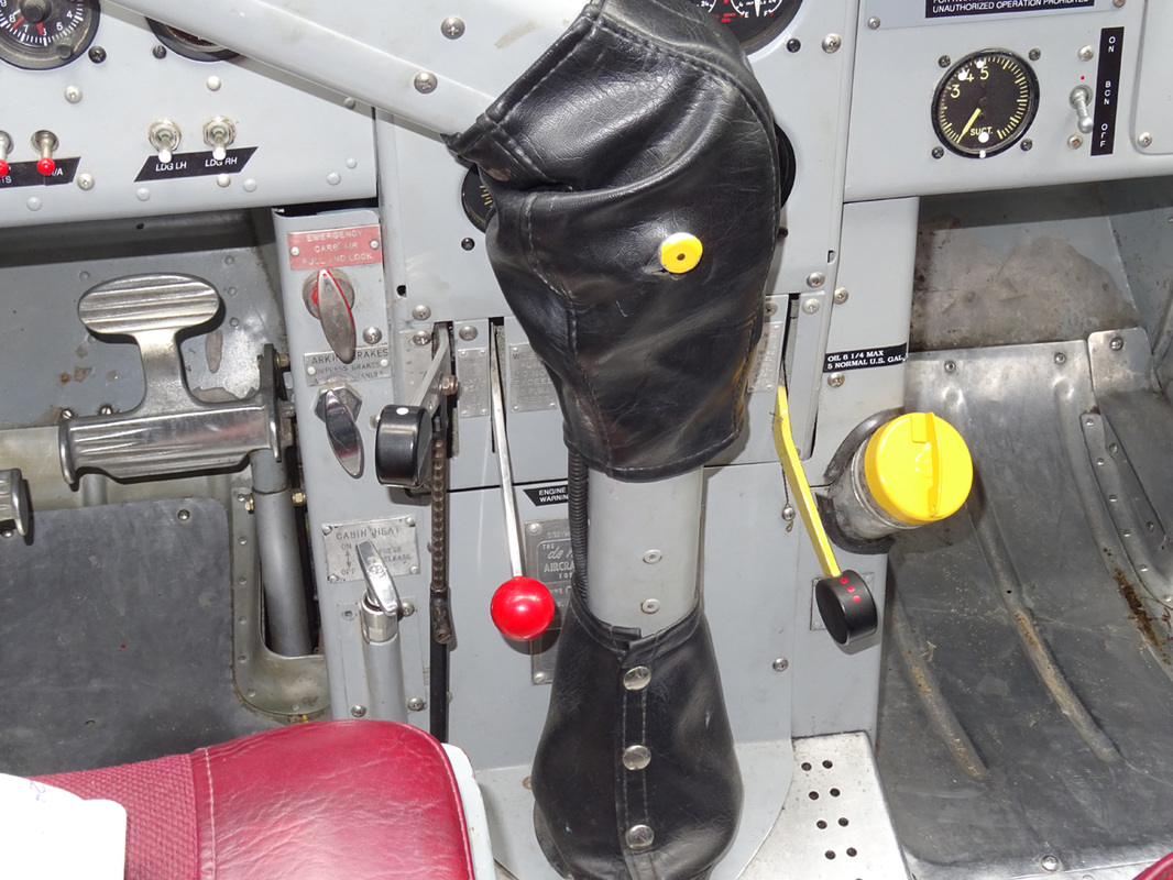
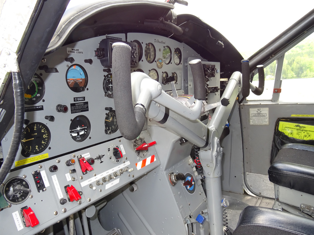
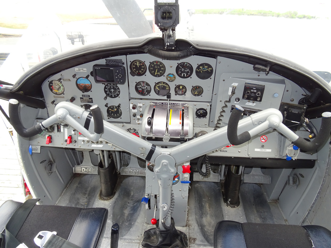
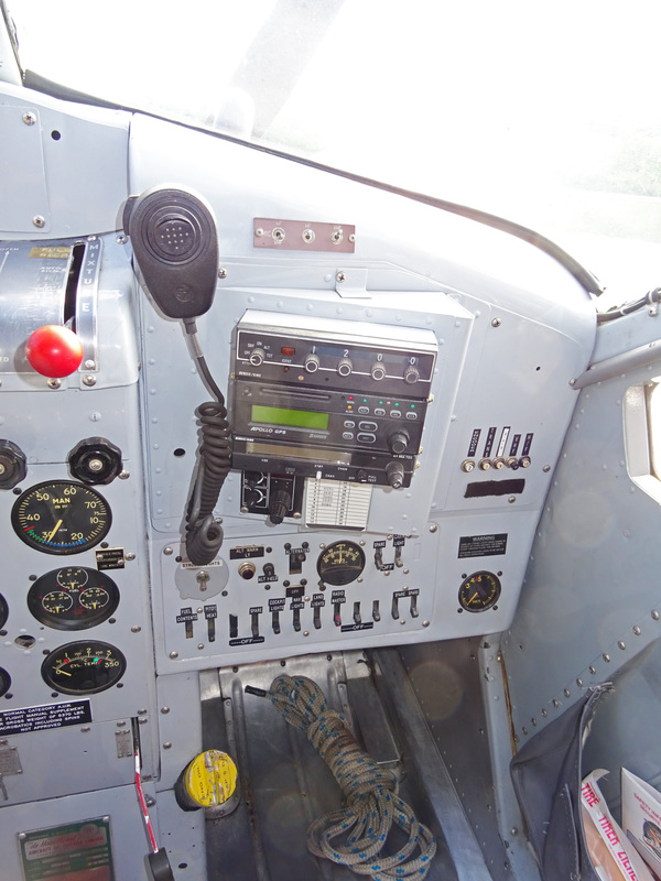
Note the yellow painted oil-filler cap at the base of the control column. This design feature allows easy access for oil fill during flight! The oil tank is located aft of the fire-wall and is serviced from inside the cockpit through a filler at the base of the pedestal. The capacity is 5 ¼ imperial gallons.
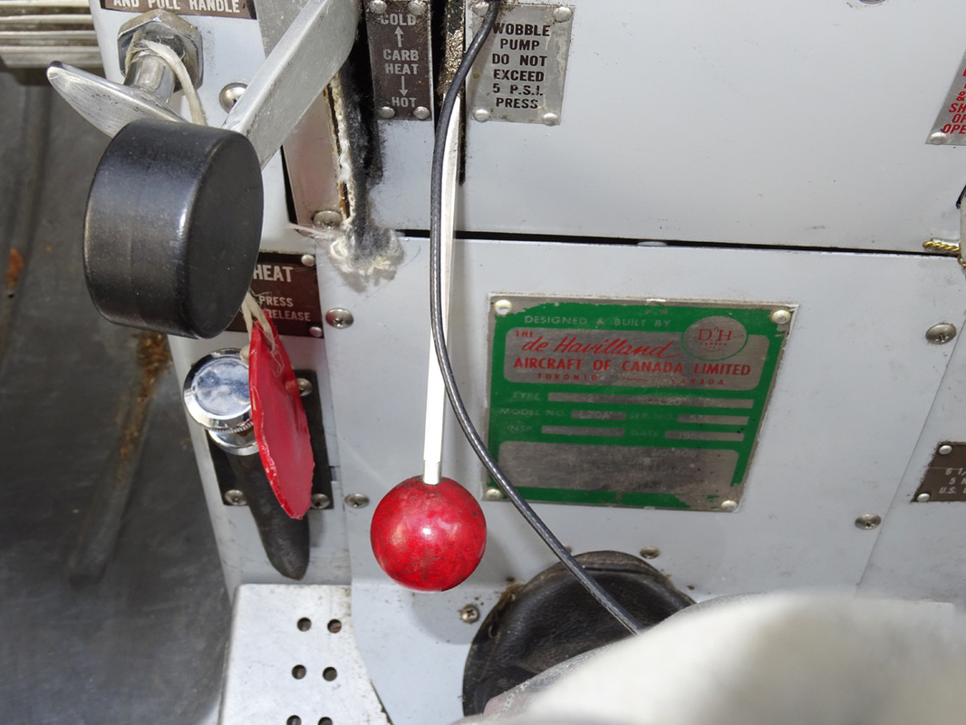
The carburetor heat control lever is located below the engine instrument panel and is cable-connected to a gate valve in the carburetor air intake duct. When the lever is selected up to the COLD position, cold ram air enters the carburetor through the air intake duct. As the lever is moved down towards the HOT position, the gate valve progressively closes the cold air intake while opening the warm air duct. This second duct allows heated air, from inside a heat exchanger muff surrounding a section of the engine exhaust collector, to mix with the cold ram air before delivery to the carburetor. Intermediate position of the lever between fully up and fully down will therefore give varying degrees of carburetor air intake temperature. With the lever in the HOT position the ram air intake is fully closed and heated air only is ducted to the carburetor. For operation in desert areas a dust filter for the ram air intake can be installed. |
The emergency shut-off lever (yellow/black knob) , on the right side of the pedestal, below the engine instrument panel, is normally wire locked in the down position. When pulled sharply up to break the wire lock and moved to the closed position, it cuts off the supply of both fuel and oil to the engine.
An emergency air handle, marked EMERGENCY CARB AIR-PULL & LOCK, is provided at the left of the engine controls pedestal. Operation of the handle mechanically opens a flap valve in the duct directly below and leading into, the carburetor. The flap valve is opened by turning the handle counterclockwise, thus breaking the lock wire. The handle is then pulled fully out and turned clockwise to lock the flap valve fully open. In this position an emergency air inlet to the carburetor is provided, in the event of a blockage in the main induction system. In many float equipped Beavers one still can find the parking brake. Its located on the left side of the pedestal, just above the wobble pump handle. |
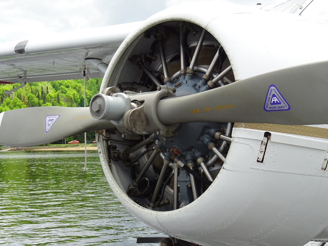
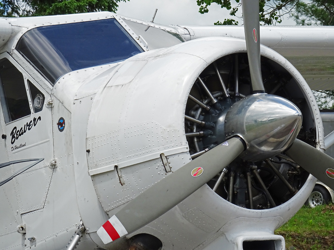
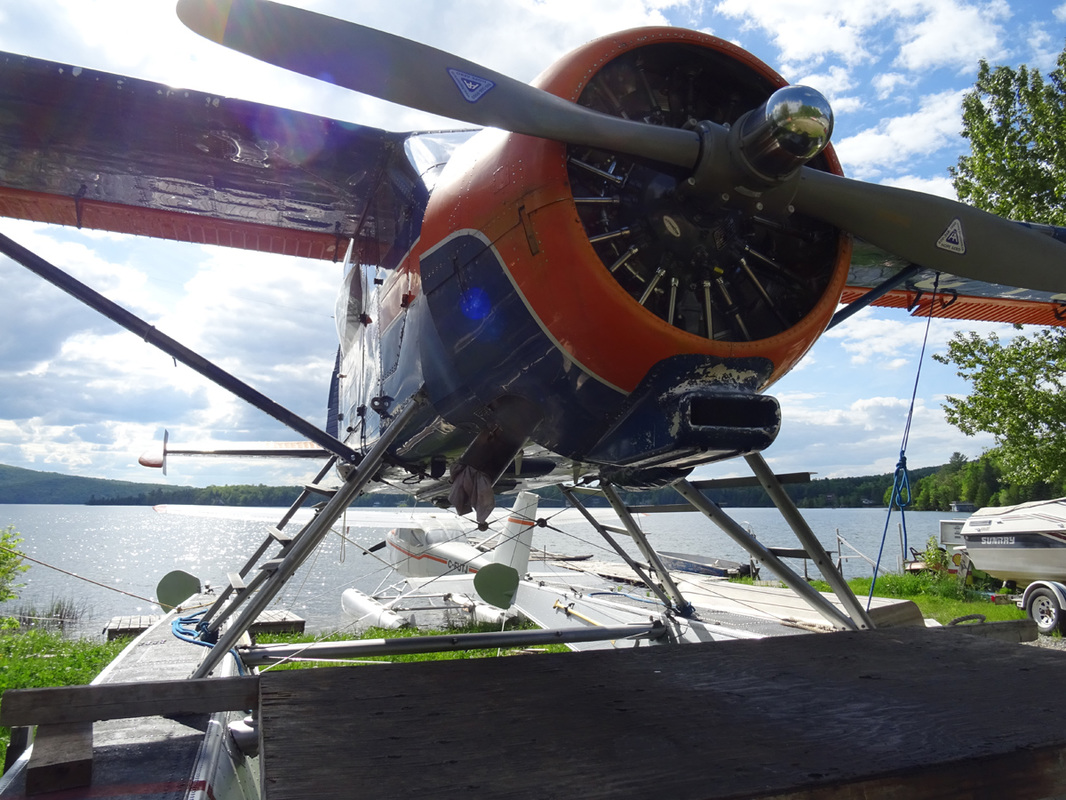
The aircraft is powered by a Pratt & Whitney ‘Wasp Junior’ model R-985SB3 nine-cylinder single-row radial engine, rated at 400 BHP at 5,000 ft altitude. The engine drives a Hamilton-Standard constant-speed propeller; crankshaft and propeller rotation being clockwise. The supercharger is an engine-driven single-stage centrifugal type. Propeller diameter measures 8 ft. 6 in.
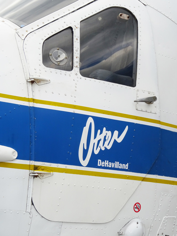
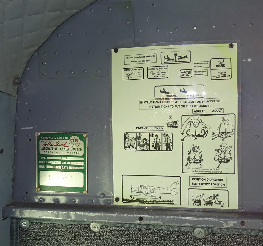
The Otter was built in response to a need for an aircraft like the Beaver, but twice as large. The Otter had good load-carrying ability, great reliability, and excellent short take-off-and-landing capabilities, all of which recommended it for both civil and military use. The US Army and US Navy used Otters and the RCAF operated 69, some of which served overseas on United Nations duties. Otters also served with nine other air forces, and civilian versions flew in 36 countries. About 450 were made.
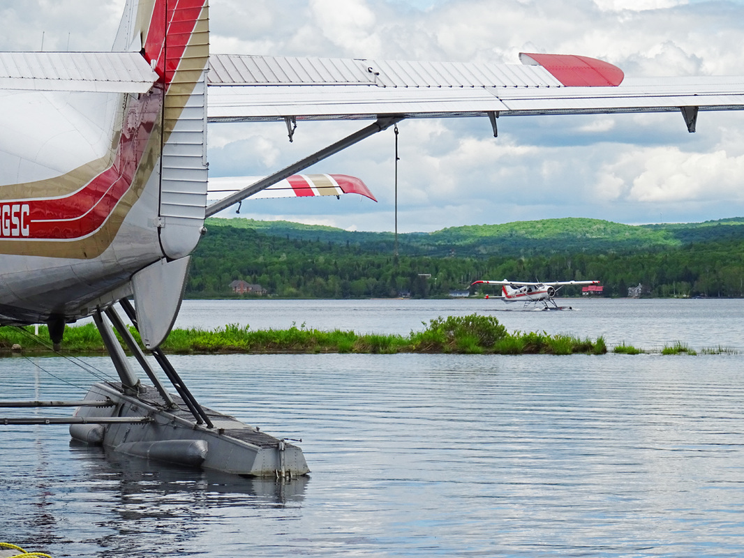
Clouds moving across the sun create a dramatic sky as C-FTUR, showing a bit of rudder and elevator, pulls away for the Air Mont-Laurier dock at Lac Tiberiade.
Built in the 50's, you gotta love and admire these back country work horses - especially in these settings.
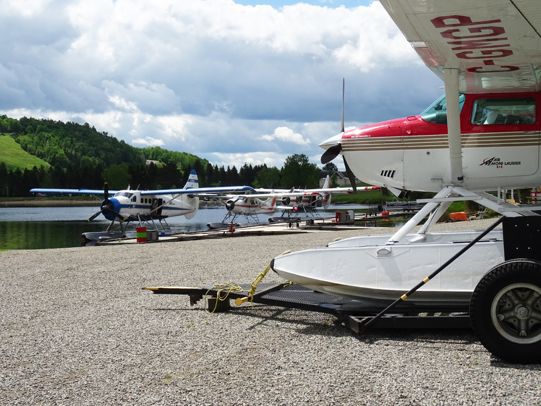
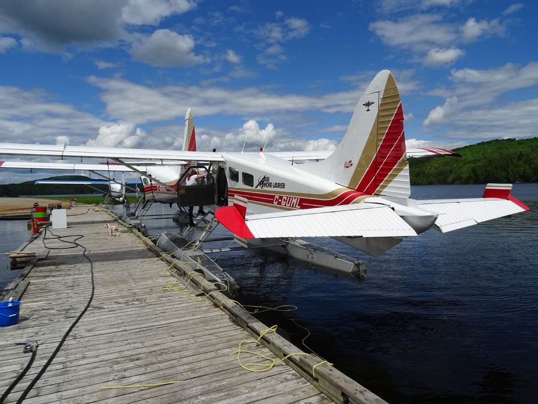
Clouds moving across the sun create a dramatic sky above the Air Mont-Laurier fleet.
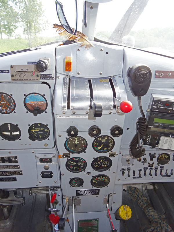
PROPELLER CONTROL
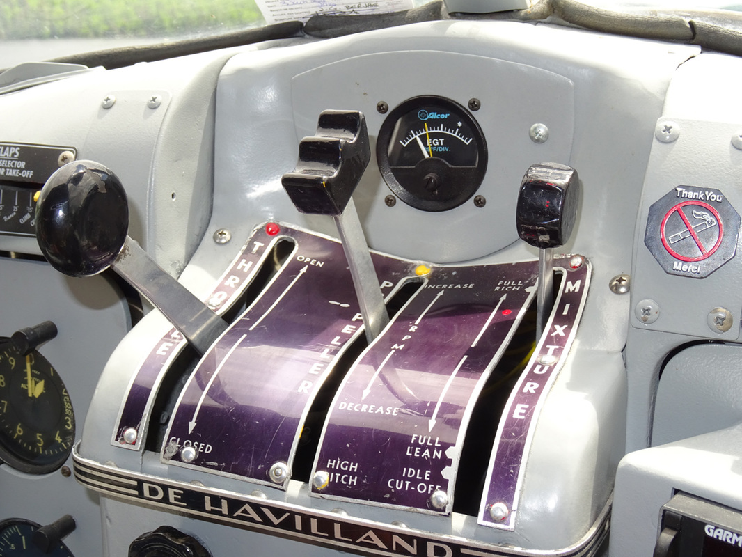
The engine RPM are determined by the setting of the propeller control lever located on the quadrant on top of the pedestal. The control lever is connected to the propeller governor by a flexible cable and slides in a gate marked HIGH PITCH, DECREASE RPM and INCREASE RPM. The propeller governor automatically maintains any selected rpm within the operating range of the propeller, regardless of variation in air loads or flight attitudes. A friction control below the propeller control lever prevents the lever from creeping when rotated clockwise. The governor maintains the propeller blades within the constant speed range by supplying oil at engine pressure to the outboard end of the propeller actuating piston which, together with the centrifugal twisting moment acting on the blades, tends to move the blades towards low pitch. To balance the effect of both these forces, engine oil is boosted in pressure by the engine driven propeller governor and is passed to the inboard end of the propeller actuating piston to the blades towards high pitch. The propeller pitch can be changed by reselection of the propeller control lever which varies the load on the governor fly-weight and allows the governor pilot valve to take up a new position to maintain the propeller at the new selected constant speed setting.
The engine RPM are determined by the setting of the propeller control lever located on the quadrant on top of the pedestal. The control lever is connected to the propeller governor by a flexible cable and slides in a gate marked HIGH PITCH, DECREASE RPM and INCREASE RPM. The propeller governor automatically maintains any selected rpm within the operating range of the propeller, regardless of variation in air loads or flight attitudes. A friction control below the propeller control lever prevents the lever from creeping when rotated clockwise. The governor maintains the propeller blades within the constant speed range by supplying oil at engine pressure to the outboard end of the propeller actuating piston which, together with the centrifugal twisting moment acting on the blades, tends to move the blades towards low pitch. To balance the effect of both these forces, engine oil is boosted in pressure by the engine driven propeller governor and is passed to the inboard end of the propeller actuating piston to the blades towards high pitch. The propeller pitch can be changed by reselection of the propeller control lever which varies the load on the governor fly-weight and allows the governor pilot valve to take up a new position to maintain the propeller at the new selected constant speed setting.
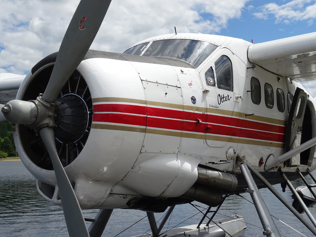
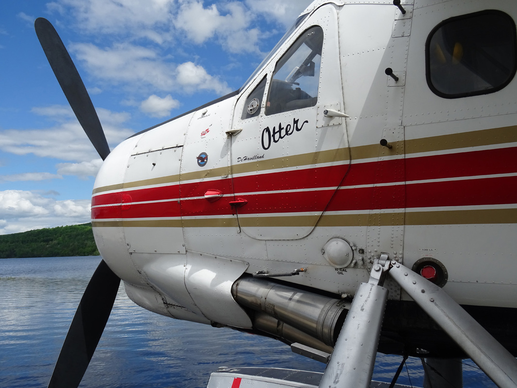
The airplane is powered by a Pratt & Whitney Wasp R-1340, geared nine cylinders, air-cooled, radial, supercharged engine rated at 600 BHP. The supercharger is of the direct-connected, engine driven centrifugal type and is not under control of the pilot. The engine is burning 40 Imp. gallons per hour.
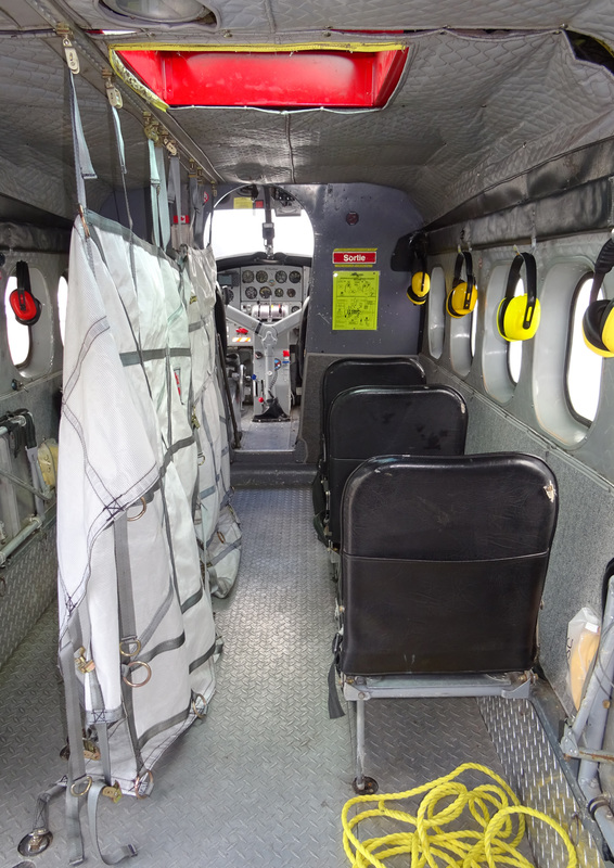
The unusually wide cabin doors, combined with the generous cabin dimensions and folding passenger seats provide rapid flexibility in mixed passenger/cargo ratios. The left double freight doors open to 118 cm and the right one to 76.2 cm . These and many other features are essential to quick turn-around-time
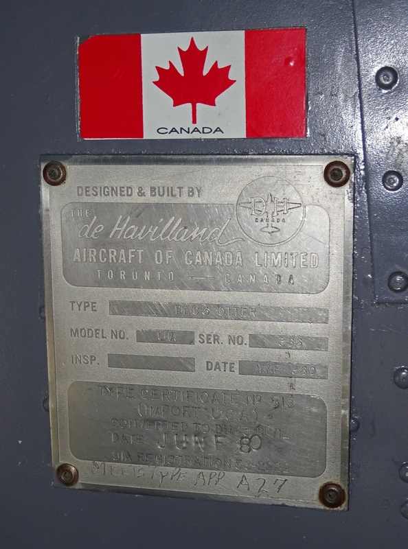
Otter C-GGSC was delivered new to the United States Army during May 1960. After military service she was sold to aircraft broker Waggoner Aircraft Inc. After passing through the hands of further bush-plane operators it joined Air Mont-Laurier (1985) Inc. of St. Veronique during April, 1988.
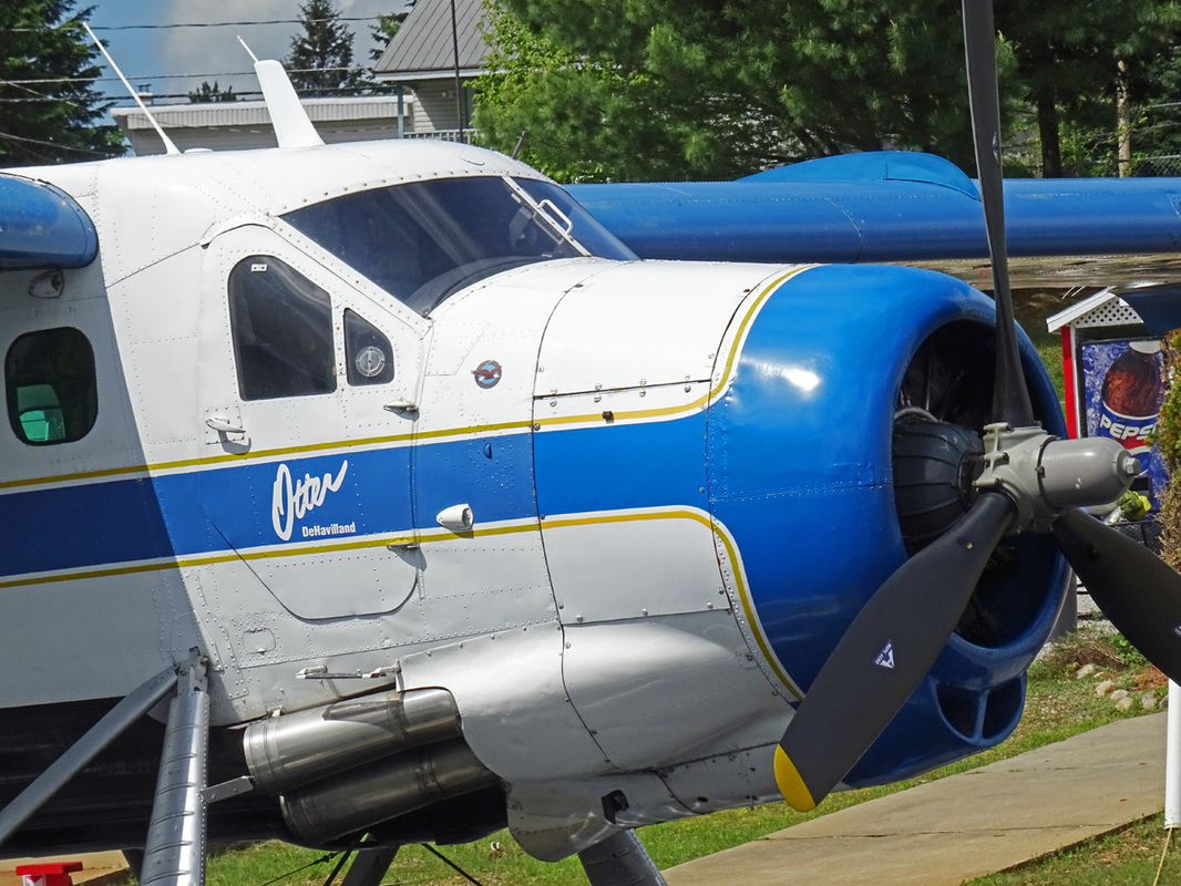
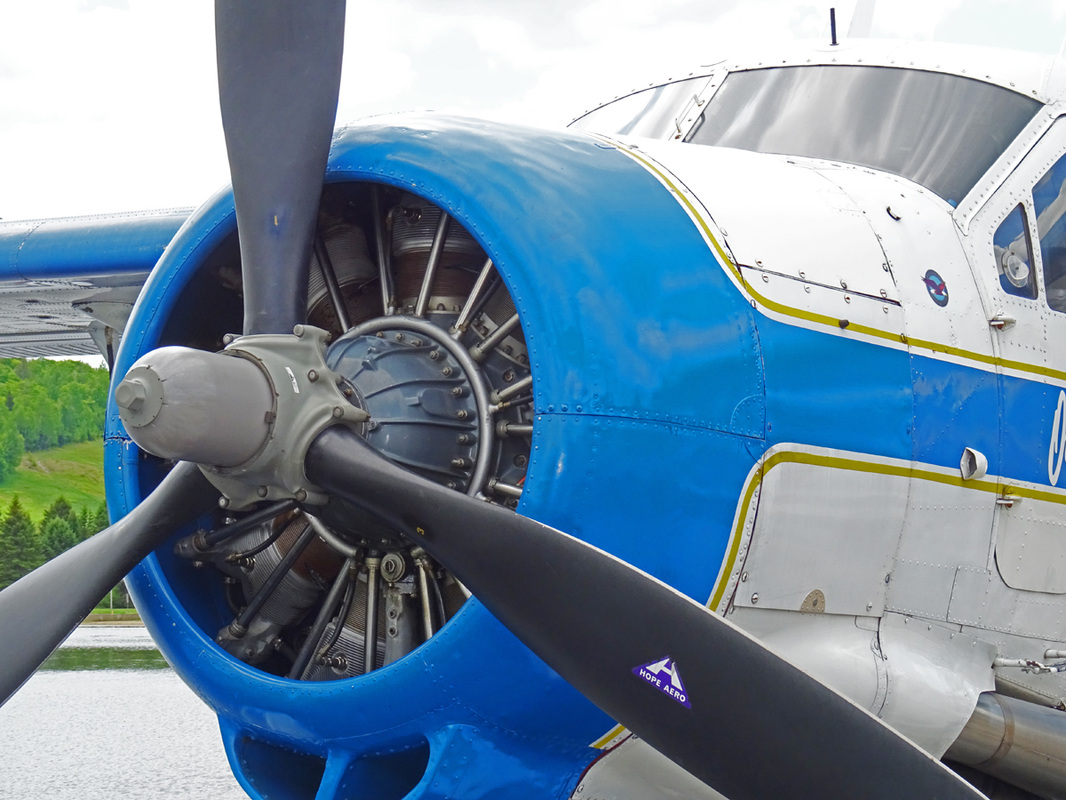
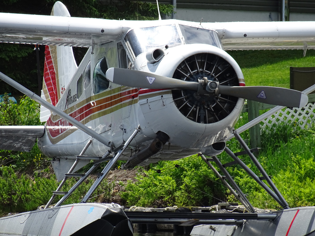
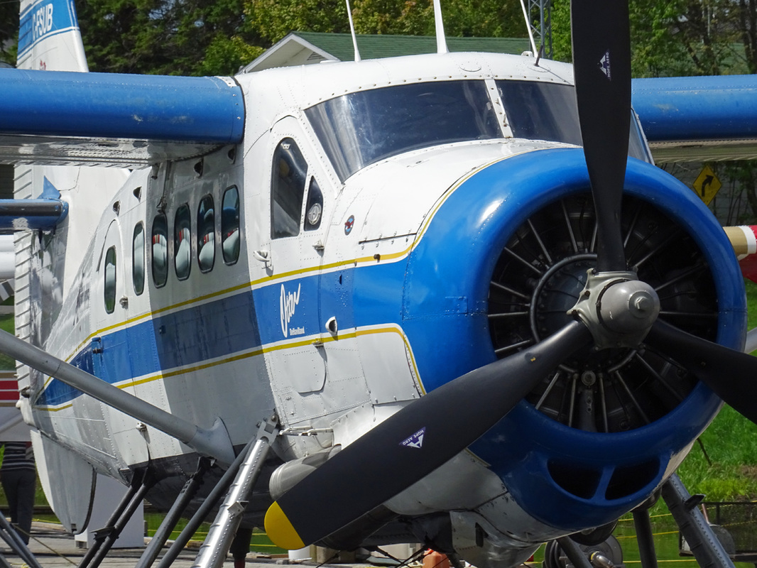
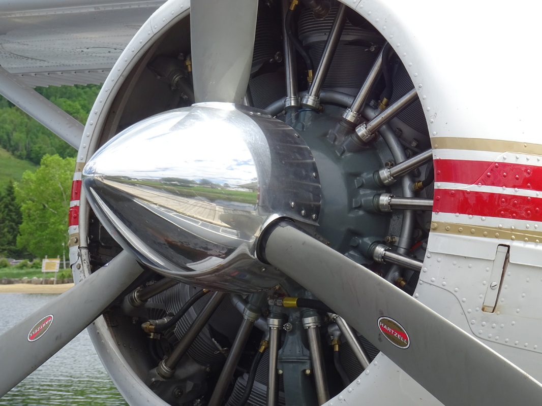
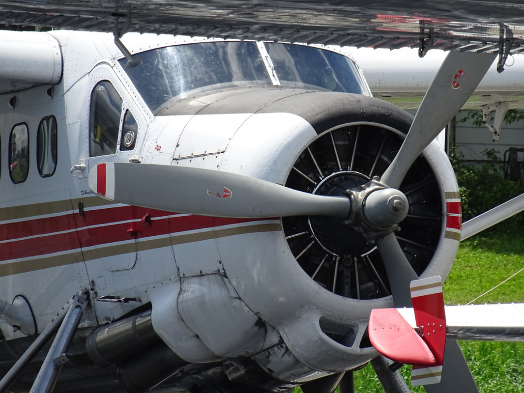
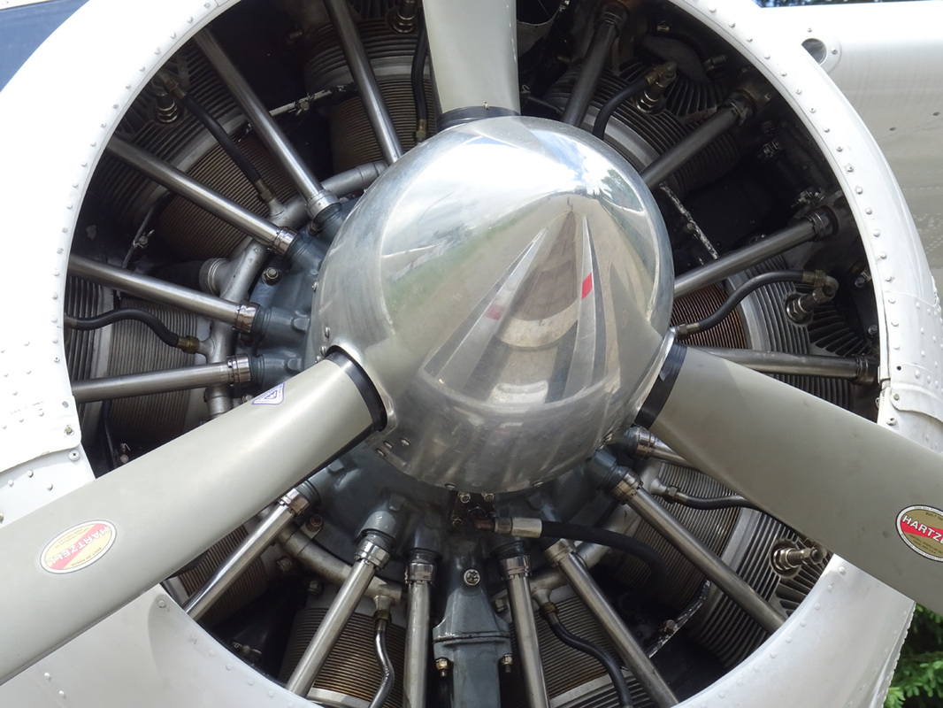
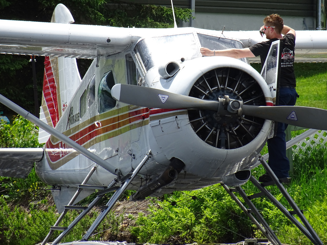
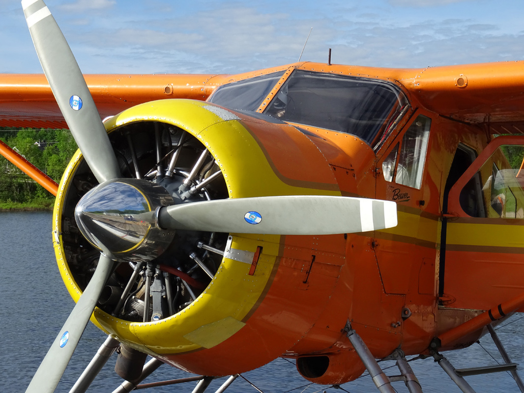
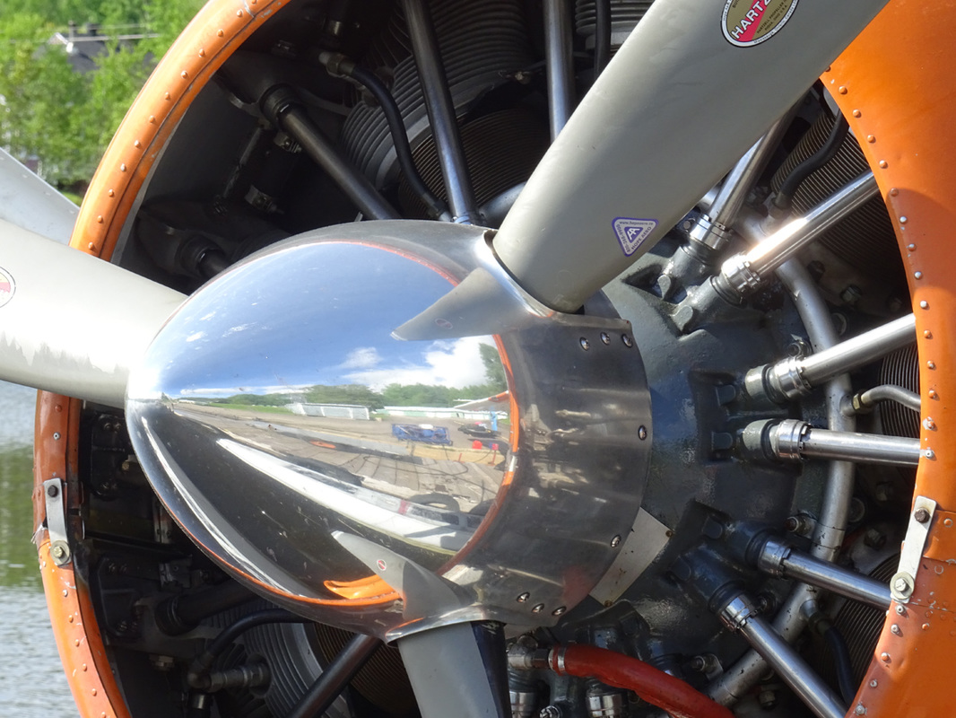
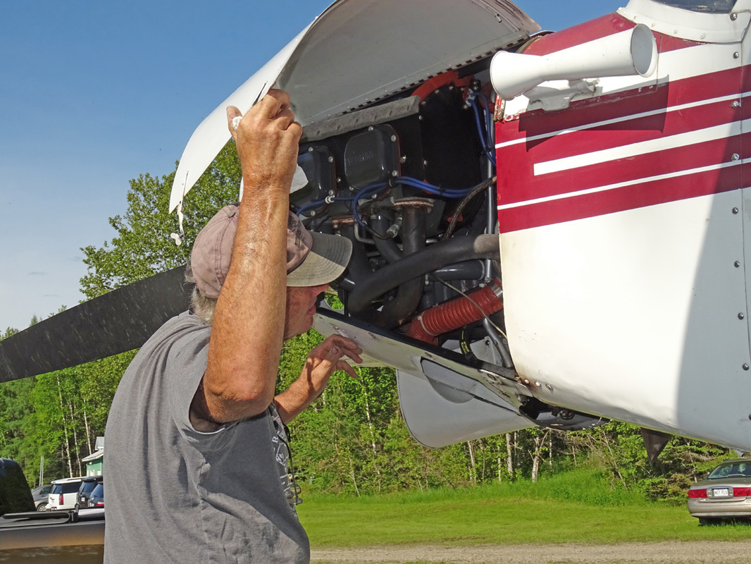
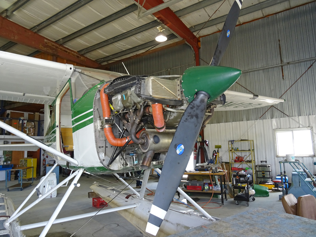
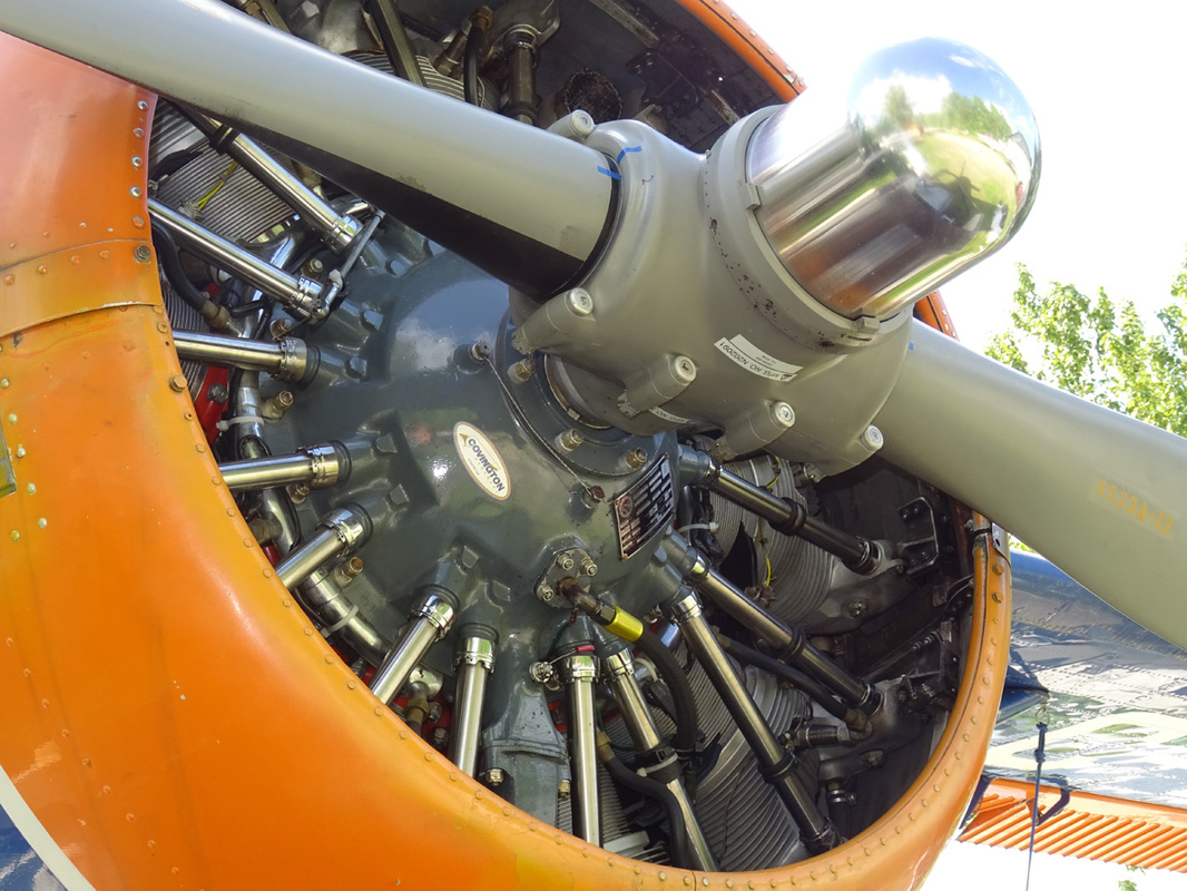
A very nice close up view of a Pratt & Whitney R-985 and R-1340.
C-GUML. The history of this DHC-2 Beaver is relative short. It was delivered in 1952 to the USAF and served with the USAF 606th Air Commando Squadron at the Nakhan Phanom, Royal Thai AFB Thailand, until circa 1967. She was returned to the U.S. and sold to a aircraft broker. Several months later she was imported into Canada during 1976 and registered to Air Mont Laurier as C-GUML.
Three-Blade Propeller. Due to its shorter diameter, the three-blade propeller is smoother, quieter and less subject to blade damage than a two-blade propeller. There's also a weight saving of 56-61 pounds and a cost saving of up to 50 percent at overhaul time.
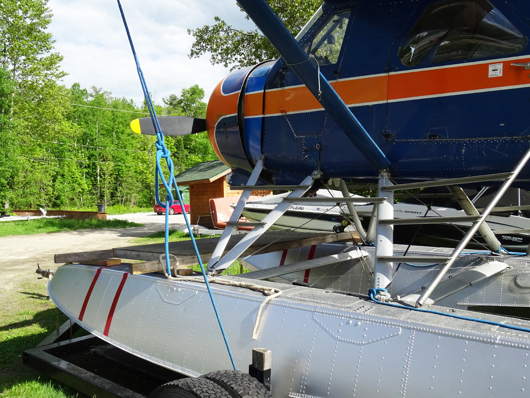
Port side view of C-GUML at its base in St. Veronique, Quebec, on Lac de Tibériade.
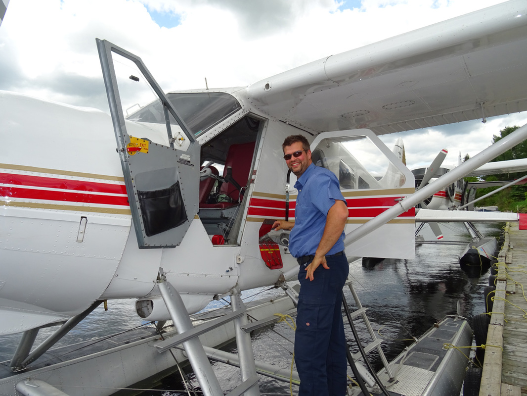
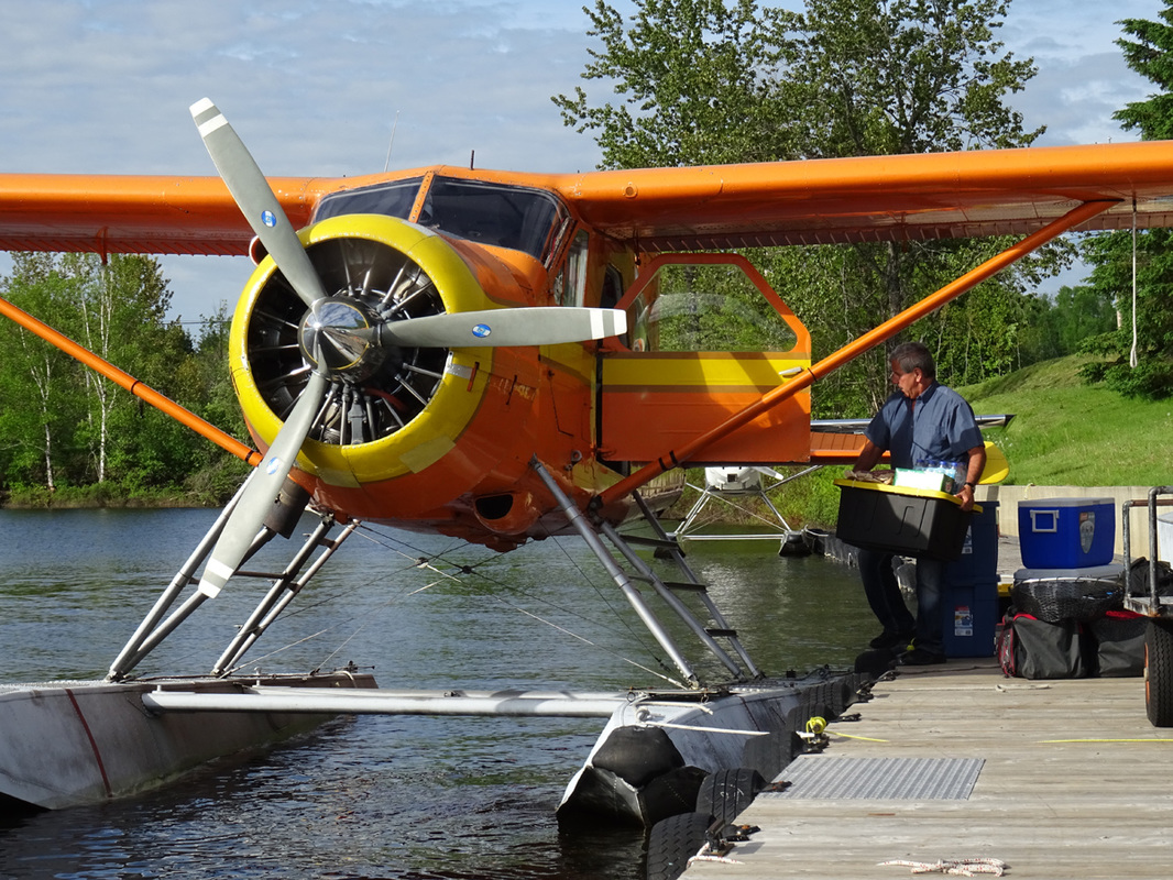
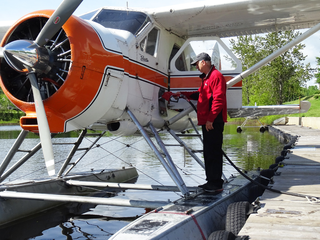
Air Mont-Laurier DHC-2 Beaver C-FTUR is being fueled for her next flight.
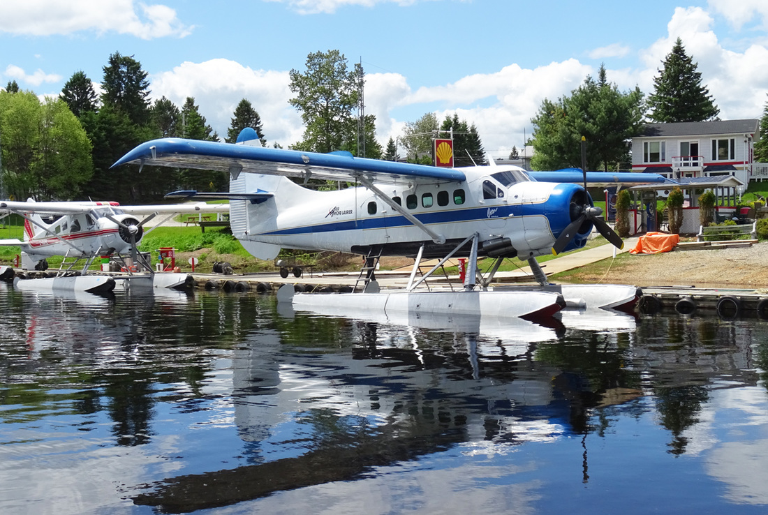
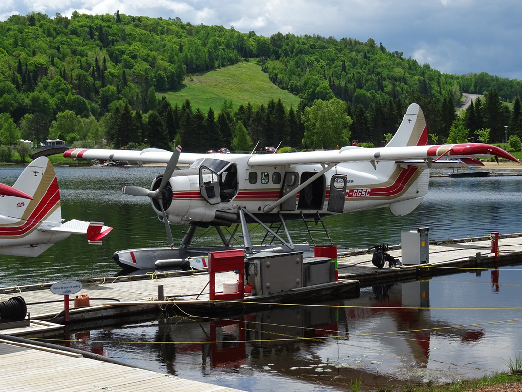
One can see the aircraft reflection in the water
C-GGSC a 1959 built Otter is enjoying the tranquility of home base on Lac Tibériade.
Pratt & Whitney R-1340
The first R-1340 developed 425 hp. The engine remained in production until 1960 with the last variants producing up to 600 hp, which is still the engine in the standard Otter. With almost 35,000 R-1340 build over the years, the engine is the power plant for the Noorduyn Norseman, Harvard, the Fairchild 71C and Super 71 and of course the DHC-3 Otter.
The original R-1340 radial engine used in the Otter has been out of production for many years. Parts are becoming scarce and overhauls expensive. The Otter’s airframe though, was designed to last and conversions with turbo powered engines will keep the Otter flying for many more decades.
The cabin is 1.5 meter by 1.5 meter wide and has an overall length of 5 meter . This provides a total volume of 9,8 cubic meters and includes the rear stowage compartment which is separated by a removable bulkhead. The cabin interior is fitted to accommodate nine passengers, eight passenger seats in the cabin and one beside the pilot. The seats can be folded against the cabin wall to enable all of the cabin space to be utilized for cargo. If desired, they can also be quickly removed and their weight deducted to obtain additional freight payload. With the seats folded, the Otter becomes literally a ‘flying truck’, capable of handling heavy loads of bulk cargo
An Otter reflection on a very calm and beautiful Lac de Tibériade!
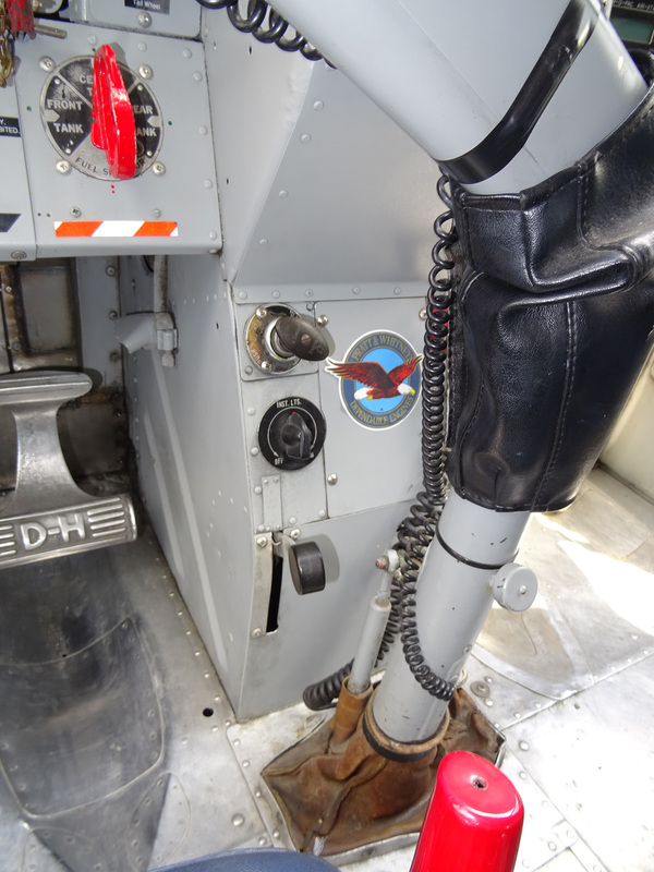
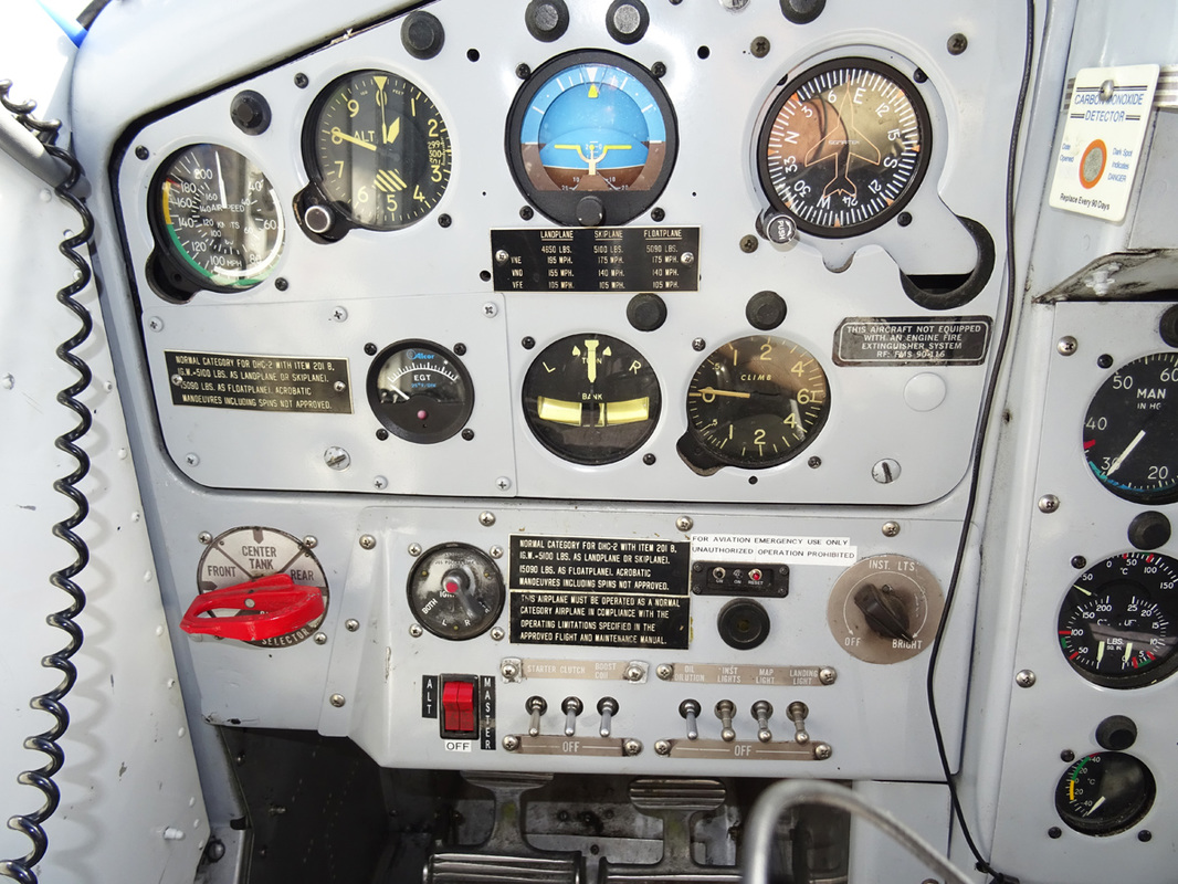
The engine ignition switch is located on the starter panel below the pilot’s flight instrument panel. The switch is marked OFF, R, L and BOTH.
The carburetor hot air control lever is located on the left side of the base of the pedestal and is mechanically linked to a barrel valve in the carburetor air intake. When the lever is in the COLD position, cold ram air enters the carburetor through the shielded air intake. As the lever is moved downwards towards the HOT position, the barrel valve progressively closes the ram air intake while it opens another duct. This second carburetor air duct allows heated air from the inside of a heat exchanger muff which surrounds a section of the engine exhaust collector, to mix with the cold ram air before delivery to the carburetor. Thus, intermediate positions of the lever between fully up and fully down give varying carburetor air intake temperatures. With the carburetor air control lever in the HOT position, the ram air intake is fully closed and hot air from the heat exchanger muff only is ducted to the carburetor. The resulting mixture temperature is indicated on the carburetor mixture temperature gage.
The hand-operated cylinder primer pump injects fuel into cylinders numbers 1, 2 , 3, 8 and 9. It is located on the left side of the pedestal, below the engine controls quadrant. To unlock the primer, the pump handle is to be pushed in and rotated anti-clockwise. After use the primer pump handle must be relocked by pushing in and rotating clockwise in order to prevent engine flooding and a fire risk when the booster pump is switched on.
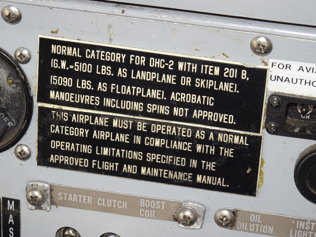
The engine is started by an electrical, direct-cranking starter. The starter switch for the electrical direct-cranking starter motor and the two starter switches required for the electrical inertia starter are located on the starter panel below the flight instrument panel. The switch or switches are spring-loaded to the OFF position.
A boost coil switch is located on the starter panel. This switch is also spring-loaded to the OFF position.
The engine drives either a Hamilton Standard, three bladed, constant speed, counterweight type propeller or a Hamilton Standard, three bladed, hydromatic, non-feathering propeller.
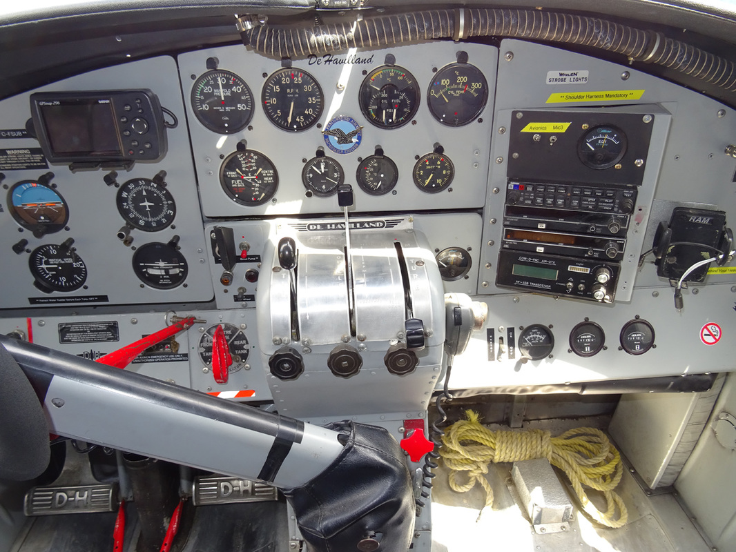
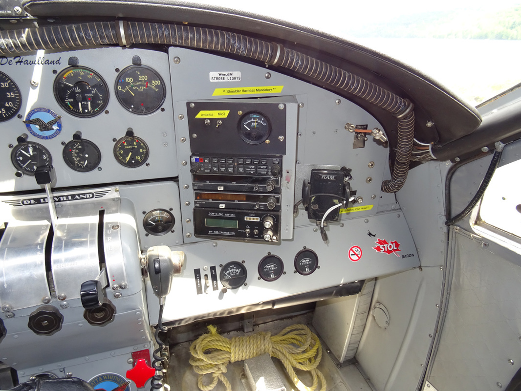
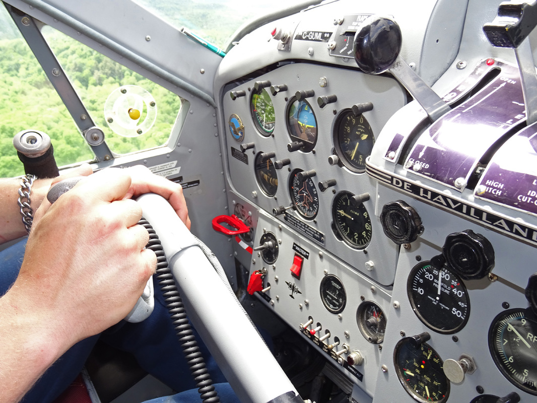
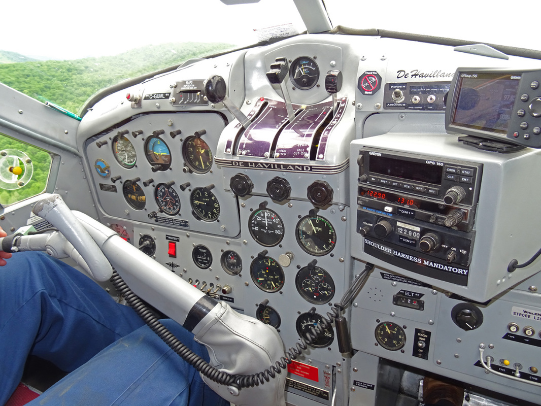
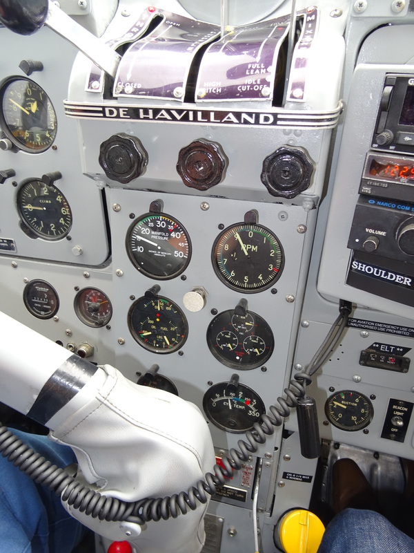
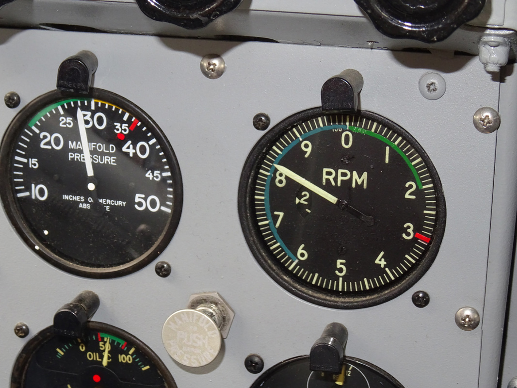
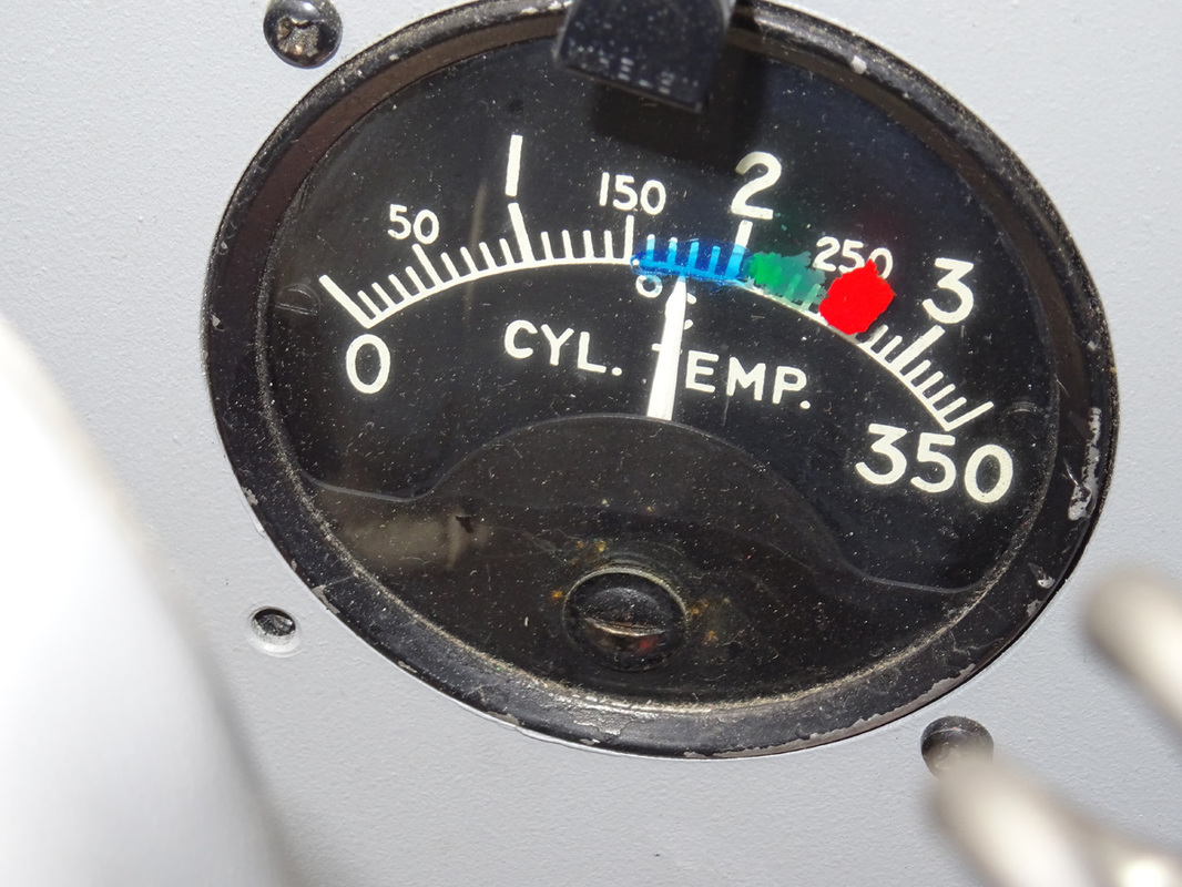
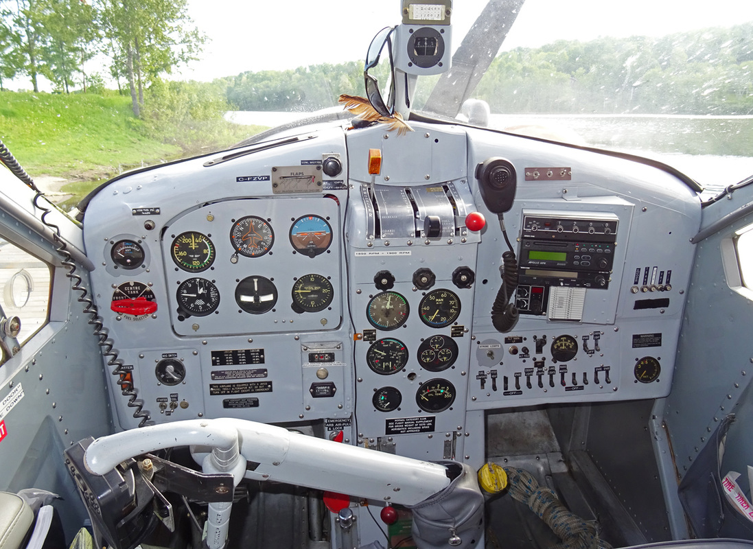
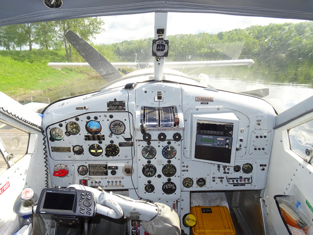
Conventional engine instrument are mounted on a panel above the engine controls quadrant. They consist of; a tachometer, a manifold pressure gage, a cylinder head temperature gage, a carburetor mixture temperature gage, an oil pressure gage, an oil temperature gage and a fuel pressure gage. The tachometer indicator is operated by an electrical generator driven by the engine. A triple indicator fuel contents gage and a clock are also located on the engine instrument panel.
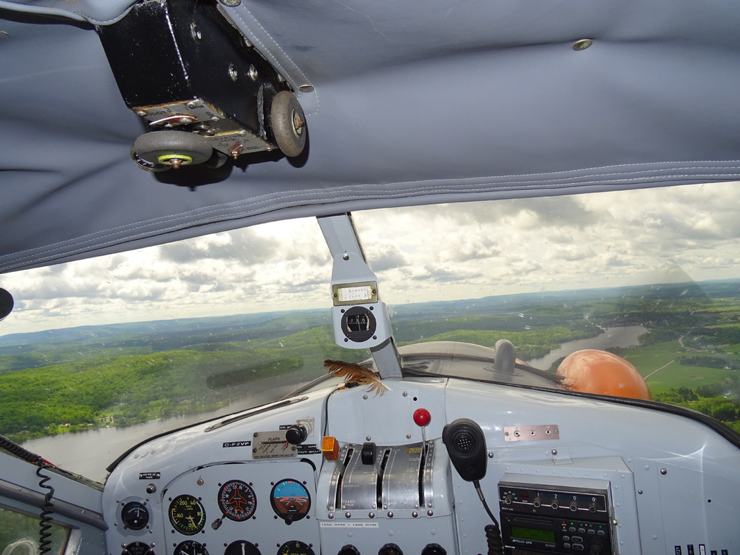
A shock-mounted flight instrument panel is provided for the pilot and incorporates the following flight instruments; Airspeed Indicator, Altimeter, Artificial Horizon, Directional Gyro, Rate-of-Climb Indicator, Turn-and-Bank Indicator, Magnetic Compass, Radio Compass and space provision for another flight or Navigation Instruments like a GPS.
Pitot-Static operated instruments comprise: Airspeed Indicator, Altimeter and Rate-of-Climb Indicator.
The engine driven vacuum pump provides suction to operate; Directional Gyro, Artificial Horizon and Turn-and-Bank Indicator.
The artificial horizon is operated by the vacuum system and gives bank, dive and climb indications. A knob at the bottom of the instrument dial adjusts the vertical position of the miniature airplane for fore-and-aft attitudes of the airplane. A caging knob permits to lock the instrument in the upright position and provides a rapid means for resetting if the operating limits of the instruments are exceeded. The operating limits are set to permit 60 degrees climbs and glides and 100 degrees right of left banks before the limit stops are reached.
The suction gage is located on the engine instruments panel. The gage is calibrated from zero to 10 in. Hg.
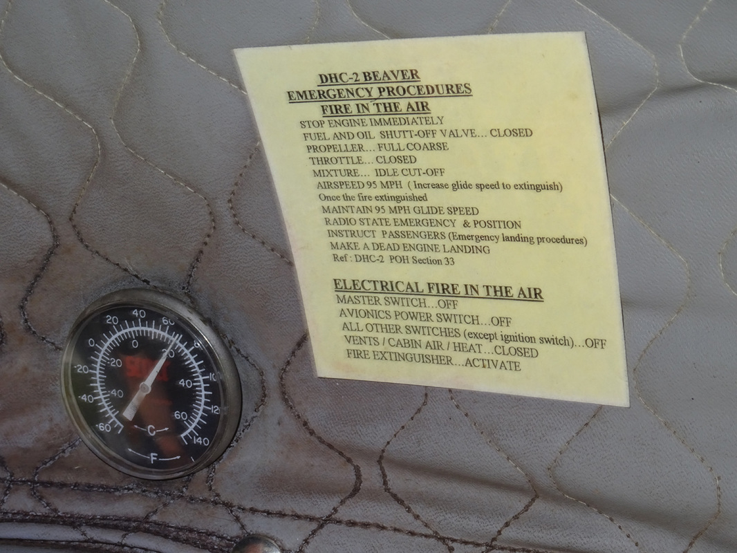
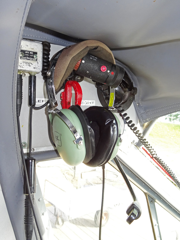
The outside air temperature gage is located in the cockpit roof. It is of the direct-reading bulb type. Its dial is graduated in degrees Fahrenheit and Centigrade.
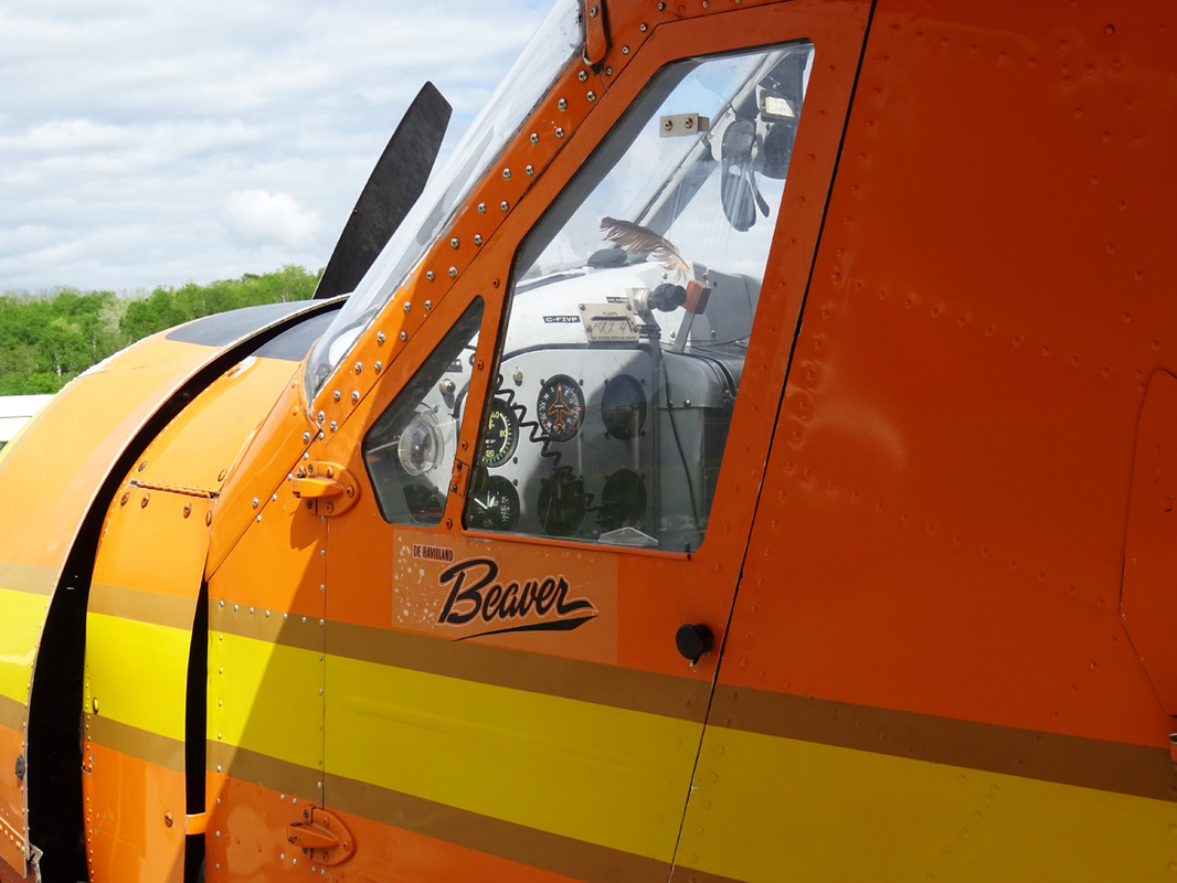
Note the matte black anti-glare paint on the area in front of the windshield of both the Otter
Engine controls. The throttle control lever at the left of the quadrant at the top of the pedestal slides in a gate marked CLOSED and OPEN. The lever is connected by a flexible cable and conduit control to the carburetor throttle valve. A friction control below the throttle lever prevents throttle creep when rotated clockwise.
The fuel air mixture ratio is manually determined through the mixture control lever at the right of the quadrant. Reading from the rear to the front, positions marked on the quadrant gate are: IDLE CUT-OFF, FULL LEAN and FULL RICH. A friction control knob below the control lever prevents the control from creeping and permits to set any intermediate position, when tightened clockwise.
The fuel selector handle, located below the bottom right corner of the pilots instrument panel, can be positioned to FRONT TANK, CENTER, REAR TANK or OFF. When the engine is not operating, the selector handle must be selected to OFF to prevent drainage of the fuel supply line into the tank.
The fuel booster pump switch is located on a panel to the left of the engine controls quadrant.
A combined fuel pressure, oil pressure and oil temperature gage is located on the engine instrument panel above the engine controls quadrant.
The triple indicator fuel contents gage, graduated either in Imperial or U.S. gallons, will indicate only when the FUEL CONTENTS circuit-breaker is set. This switch is located on the junction box circuit-breaker panel, behind the copilot’s seat.
A warning light gives an indication of low fuel level in the tank from which the engine is operating. The light becomes illuminated when fuel for approximately 15 minutes of cruising remains in the tank.
|
The shut-off control handle stops the supply of both fuel and oil to the engine in case of emergency. It is located on the right side of the pedestal, below the engine controls quadrant. Electrical energy is supplied by a direct current 50 amp. 28-30 volt generator in conjunction with a 24 volt 24 amp-hr. storage battery. Installations of generators of 80 to 100 amp. and batteries up to 35 amp-hr. have been made. All circuits of the electrical system are protected by manual reset-type circuit-breakers on the junction box panel behind the co-pilot’s seat or on the electrical switch panel on the co-pilot’s sub-panel. The battery is inside the baggage compartment on a shelf in the rear right-hand corner. The following equipment and controls are supplied by the electrical system; engine starter, booster coil, fuel booster pump, pitot head heater, engine fire ext. system, instrument and warning lights, interior lights, navigation lights, landing lights, heater installation, radio and communication equipment. For starting the engine or for electrical ground checks, an external power source may be connected to an external power receptacle fitted to the right side of the fuselage, aft of the cabin door. Access is gained through a spring-loaded hinge panel. When external power is connected, the aircraft battery is isolated if the battery master switch is in the OFF position. The battery master switch on the starter panel, is of the double-pole, single-throw type and serves also as the generator field switch. A volt-ammeter is on the electrical switch panel. The instrument constantly shows the number amps. being delivered to the system and the battery. When pressing the button on the left side of the instrument, the generator output voltage is indicated. All control surfaces are mass-balanced and are conventionally operated by a control column and rudder pedals. The handwheel portion of the control column may be ‘thrown-over’ for use by a co-pilot, in conjunction with the installation of rudder pedals on the right side of the cockpit. The wing flaps are of the full-span, double-slotted type. The outboard trailing edge portions of the flaps are operated independently as ailerons. The incidence of the tailplane may be adjusted in flight by rotating the TAILPANE TRIM handwheel at the right side of the pilot’s seat. The handwheel operates in the natural sense and its pointer moves over a label marked NOSE DOWN, TAKE OFF SETTING and NOSE UP. The area marked TAKE OFF SETTING is edged in green. The neutral position of the tail-plane trim is marked 0 with further markings to 2 in the NOSE DOWN direction and to 5 in the NOSE UP direction. The rudder trim tab is actuated by a handwheel in the cockpit roof. The handwheel assembly incorporates a position indicator which moves over a scale marked L and R indicating the direction an amount of trim applied. The aileron trim which is adjusted by means of a handwheel on the control column varies the tension left or right of the aileron control cable in flight. Fixed trim tabs on each aileron are provided for adjustment on the ground by qualified servicing personnel. The pilot’s rudder pedals may be adjusted for leg reach. By pulling the adjusting knob, the pedals can be moved to the desired position and secured in that position by releasing the adjusting knob. The wing flaps are operated hydraulically by a flap actuating jack assembly, located in the fuselage roof between the front and rear wing attachment lugs. Hydraulic fluid, contained in a separate reservoir located aft of the firewall on the left-hand side, is pumped into the flap actuating jack assembly by means of a handpump located beneath the pilot’s seat. Wing flaps are selected UP or DOWN with a selector lever and after they are pumped to the desired position with the handpump, they are automatically locked by a hydraulic ratchet valve which is part of the flap actuating jack assembly. The wing flaps are mechanically connected to the trim tab on the left elevator so that actuation of the wing flaps automatically deflects the trim tab to maintain the longitudinal trim. The handpump lever is in line with the right-hand side of the pilot’s seat and is operated in a fore-and-aft movement. The wing flaps selector lever is mounted on the tailplane trim pedestal, to the right of the pilot’s seat. CRUISE, LAND, or intermediate positions of the wing flaps are obtained by moving the wing flaps selector lever to up or down position and then pumping the flaps to the desired position, as shown on the wing flaps position indicator. Note when the wing flaps have been pumped to the desired position, the wing flaps selector lever should immediately be moved to its neutral position, to provide an addition lock on flap motion. The wing flaps position indicator is located on the vertical frame member of the windshield and is marked UP, CRUISE, CLIMB, TAKE-OFF, LAND and DOWN. The engine fire extinguisher system is controlled from the fire extinguisher panel below the flight instrument panel. The system incorporate a fire extinguisher bottle, flame switch and a length of fuse wire located in the engine compartment. In the event of fire, a red warning light on the extinguisher panel is illuminated and the EXTINGUISHER SWITCH must be switched on to discharge the bottle after the engine is shut down. Both the warning light and the extinguisher circuits are protected by push-to-reset button type circuit-breakers on the fire extinguisher panel. A hand-operated fire extinguisher in a quick release clip is attached to a bracket to the left and rear of the pilot’s seat. A first-aid kit is stowed in a bag located on the right-hand cabin side between the passenger door and the rear cabin bulkhead, aft and above the door lock. A second first aid kit may be installed behind the pilot’s seat in the cockpit. A 27-inch diameter hatch has been provided in the rear cabin floor just aft of the rear cabin bulkhead normally closed by lids screwed to the floor and out skin of the fuselage. A trap door may be installed. The cabin side seats may be folded flat against the wall, flush with the base of the heater duct. The rear seat hinges up against the rear cabin bulkhead. All seats have padded backs, buoyant seat cushions and lap safety belts. Fourteen cargo tie-down rings, eight of which are permanently installed are supplied with each aircraft. Eighteen receptacles to receive the six removable cargo tie-down rings permit to secure any type of cargo. An additional number of receptacles may be provided. Relief tube may be installed in the cockpit on the right-hand side of the pedestal and in the cabin. The relief tube for the cabin is located in the baggage compartment. |
|
|
Pratt & Whitney R-1340
The first R-1340 developed 425 hp. The engine remained in production until 1960 with the last variants producing up to 600 hp, which is still the engine in the standard Otter. With almost 35,000 R-1340 build over the years, the engine is the power plant for the Noorduyn Norseman, Harvard, the Fairchild 71C and Super 71 and of course the DHC-3 Otter. The original R-1340 radial engine used in the Otter has been out of production for many years. Parts are becoming scarce and overhauls expensive. The Otter’s airframe though, was designed to last and conversions with turbo powered engines will keep the Otter flying for many more decades. |
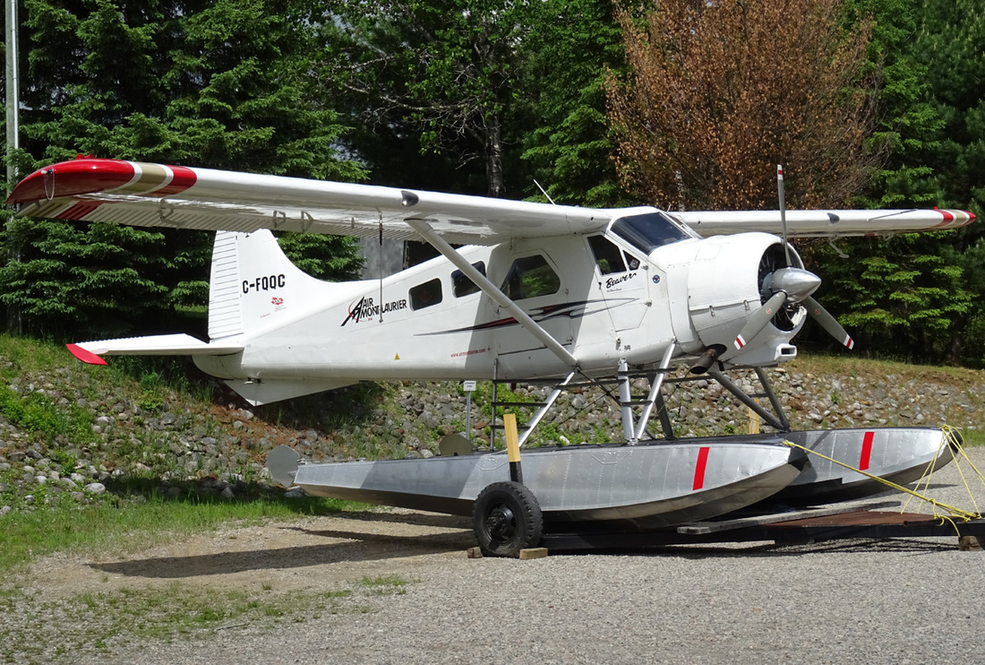
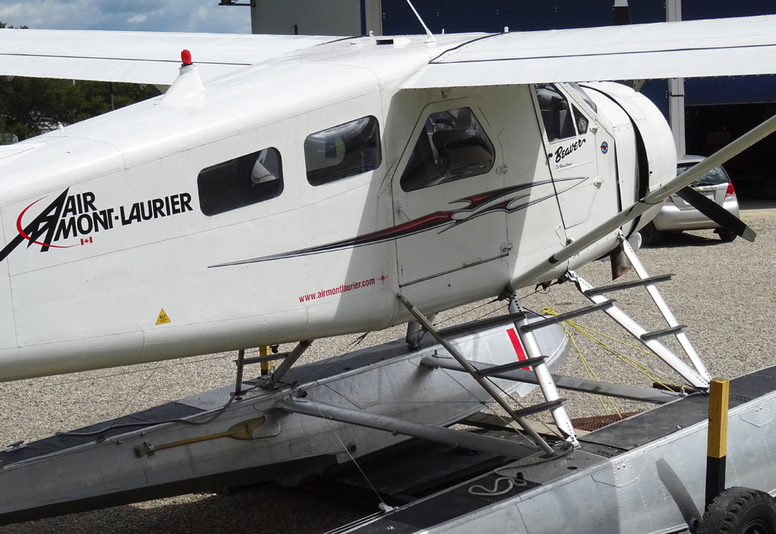
She was just sitting outside of Air Mont Laurier hangar begging me to photograph her.
C-FQQC, came off the production line in 1949 for delivery to the Peruvian Air Force. She was struck off charge 1971 and returned to Canada. Passing through the hands of further bush-plane operators she joined Air Mont Laurier (1985) in 2007.
Three-Blade Propeller. Due to its shorter diameter, the three-blade propeller is smoother, quieter and less subject to blade damage than a two-blade propeller. There's also a weight saving of 56-61 pounds and a cost saving of up to 50 percent at overhaul time.
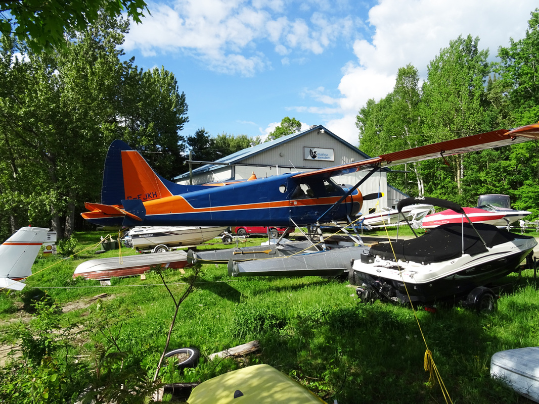
Air Mont-Laurier Beaver and Otter fleet sit at their dock on Lac Tiberiade on a crisp and clear June afternoon.
This float plane will be back at home in the water soon.
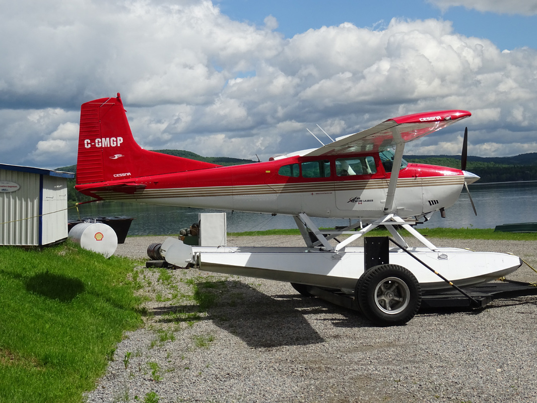
C-GMGP is a 1972 Cessna 185E Stationair II. The C-185 was introduced in 1961 as a development of the 225 hp C180. The final A185F model came out in 1973 and was the most popular. The A prefix indicated Agricultural, with crop spraying modifications available; the A was the first with the 300 hp engine. The F model has a three-bladed prop and 'camber lift' wing.
Among the more significant changes of the 1972 Model A185E were:
Among the more significant changes of the 1972 Model A185E were:
- "Ag carryall" option introduced featuring external 151 gallon chemical tank, removable spray booms with 30 nozzles, wind driven spray system, windshield wire cutters, and vertical stabilizer cable deflector.
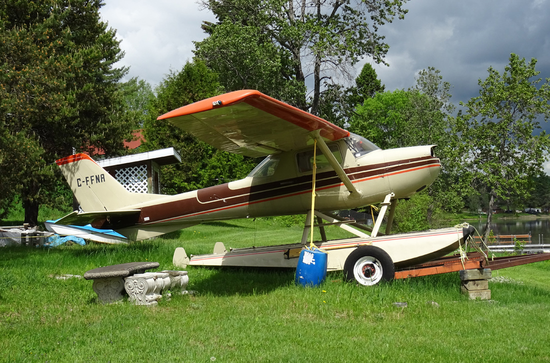
This old bird has certainly seen better days and maybe one day will fly again.
C-FFNA is a 1966 built Cessna 150G. Development of the Model 150 began in the mid-1950s with the decision by Cessna Aircraft to produce a successor to the popular Cessna 140 which finished production in 1951. The main changes in the 150 design were the use of tricycle landing gear, which is easier to learn to use than the tailwheel landing gear of the Cessna 140, and replacing the rounded wingtips and horizontal and vertical stabilizers with more modern, squared-off profiles. In addition, the narrow, hinged wing flaps of the 140 were replaced by larger, far more effective Fowler flaps.
The Cessna 150 prototype first flew on September 12, 1957, with production commencing in September 1958 at Cessna's Wichita, Kansas plant. 216 aircraft were also produced by Reims Aviation under license in France. These French manufactured 150s were designated Reims F-150, the "F" indicating they were built in France.
American-made 150s were all produced with the Continental O-200-A 100 hp (75 kW) engine, but the Reims-built aircraft are powered by a Rolls Royce-built Continental O-200-As, with some Continental O-240-A powered versions.
In the 1967 model, the instrument panel was redesigned. The doors were "bowed" out to give three more inches of shoulder and hip room which was needed in the small cabin. The "G" model also saw a new short-stroke nose oleo introduced to reduce the drag created by the nosewheel assembly. The previously fitted generator was replaced by a 60-ampere alternator, reflecting the increasing avionics that the planes were being fitted with.
The "G" model was also the first Cessna 150 variant certified for floats. A total of 2114 "G" models were built, plus 152 built by Reims as F150G.
A total of 22,138 Cessna 150s were built in the United States, including 21,404 Commuters and 734 Aerobats. Reims Aviation completed 1,764 F-150s, of which 1,428 were Commuters and 336 were Aerobats. A Reims affiliate in Argentina also assembled 47 F-150s, including 38 Commuters and 9 Aerobats.
Of all the Cessna 150-152 models, the 1966 model year was the most plentiful with 3,067 1966 Cessna 150s produced. This was the first year the aircraft featured a swept tail fin, increased baggage area and electrically operated flaps.
|
Starting at the pilot’s cockpit, make the following checks:
|
|
Watch the show!
Beaver flight around St. Veronique, Quebec. Enjoy |
|
The roar of the Pratt & Whitney R-985
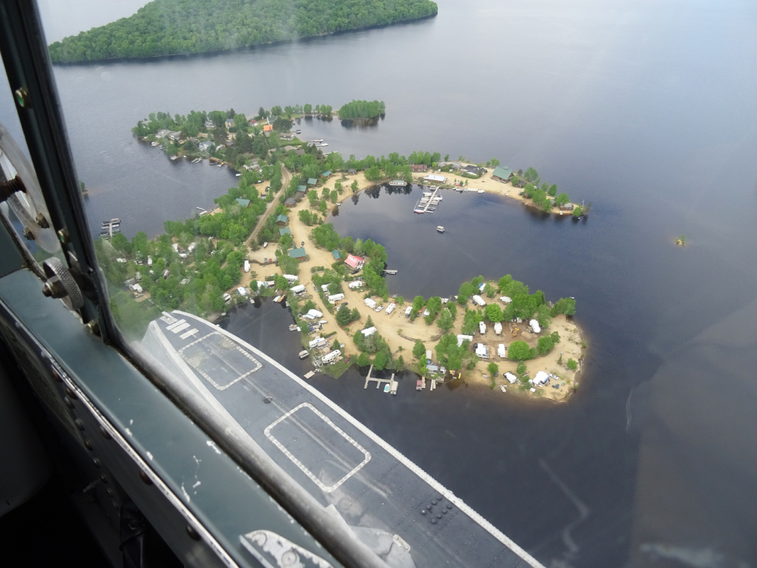
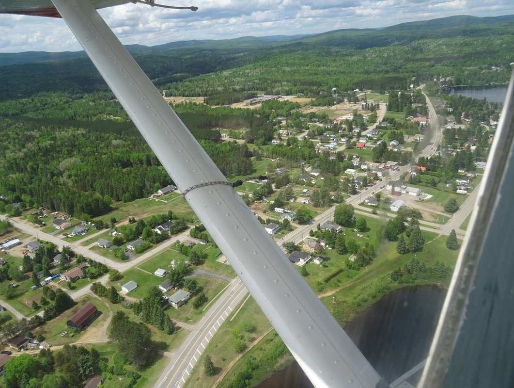
When the floatplane started its take-off run, the roar of the Pratt & Whitney R-985 Wasp radial engine reverberated off the rock outcrops surrounding the lake. The Beaver accelerated on the foaming water, rose on the ‘step’ and with gentle rearward movement on the control column she became airborne. Visibility was good and as we flew overhead the base I could see the piston Otter maneuvering on the water below. There was some chatter on the ATC frequency as we passed an unkown airsprip and thereafter unfolded a panorama of picturesque lakes and boreal forest. The handling rope on the wing was flapping in the slipstream as the flight proceeded along the many lakes and rivers.
Eric... a happy Beaver driver
A shock-mounted flight instrument panel is provided for the pilot and incorporates and altimeter, turn-and-bank indicator, rate-of-climb indicator, air speed indicator, directional gyro and artificial horizon. The airspeed indicator, altimeter and the rate-of-climb indicator, are operated by the pitot static system, The static opening is incorporated in the left-hand side of the rear fuselage. The directional gyro, artificial horizon and turn-and-bank indicator, are operated by the vacuum system. A vacuum gauge on the right of the electrical switch panel indicates the vacuum in In.Hg. being applied to the instruments.
The outside air temperature gauge is located in the cockpit roof. It is of the direct-reading bulb type and the dial is graduated in both Fahrenheit and Centigrade scales.
The outside air temperature gauge is located in the cockpit roof. It is of the direct-reading bulb type and the dial is graduated in both Fahrenheit and Centigrade scales.
The engine control quadrants are located at the top of the pedestal. Friction control knobs, one below each control lever, increase lever friction when rotated clockwise.
The throttle lever movers in a quadrant marked OPEN and CLOSED.
The lever is connected to the throttle valve by means of pus-rods and torque-tube linkage.
The mixture lever moves in a quadrant marked as follows: AUTO LEAN – AUTO RICH – FULL RICH – FULL LEAN – IDLE CUF-OFF. The lever is connected to the carburetor by means of push-rods and torque-tube linkage.
|
“Have a nice flight and many happy landings”
Starting the engine: Propeller area – clear. Battery master switch – ON Fuel and oil emergency cut-off lever – OPEN Fuel selector to the fullest tank. Mixture lever – AUTO RICH. Throttle lever – ¼ to ½ inch OPEN. Build up fuel pressure with wobble pump to maximum 5 psi. Prime 4 strokes. Both ignition switches to ON position. Hold starter switch to STARTER position until starter whine ceases ot rise in pitch. Release starter switch and simultaneously: Hold clutch engagement switch to STARTER CLUTCH position. Hold Booster Coil switch to BOOSTER COIL position. As soon as engine fires: Release Starter and Starter Clutch switches to OFF position. Release Boost coil switch. Priming Pump – locked OFF. As soon as engine fires, throttle back to about 500 to 800 rpm. Do not pump throttle to catch a ‘dying’ engine. If oil pressure does not register on gauge within 30 seconds, stop engine and investigate. As soon as oil pressure reaches 50 psi. steady indication select propeller lever to full INCREASE RPM position. Engine warm-up: Throttle to give 1000 rpm. Move propeller lever fully forward to INCREASE RPM, as soon as oil pressure reaches 50 psi. After oil temperature has reached 40 degrees Celsius (100 dgr. F), adjust to smoothest engine speed between 1000 to 1400 rpm. Mixture lever FULL RICH. Select propeller lever to coarser pitch at 1000 rpm, to circulate the oil in the constant speed unit and propeller cylinder, then return to INCREASE RPM. Never rush engine warm-up. Check oil pressure, fuel pressure and temperature. Tank feeds – check by rotating fuel selector to each tank. Take-off: Make sure cylinder head temperature is below 230 degrees Celsius (450 dgr. F). Adjust throttle lever friction knob. Line up in the wind direction. Open the throttle smoothly to maximum permissible take-off power. Anticipate tendency of aircraft to swing to the left. Allow aircraft to fly itself of at 55 to 65 mph. in a tail down attitude and climb at 65 mph. As soon as safe height has been attained, reduce power to 33.5 In.Hg. and 2200 rpm if aircraft is fully loaded, or 30 In.Hg. and 2000 rpm for normal weight. Slowly increase air speed to 80 mph and re-trim. At altitude of 500 ft. – flaps to CLIMB and re-trim. |
Av-Gas fuel burn = 50kg/hr or 20gallons/hr
|
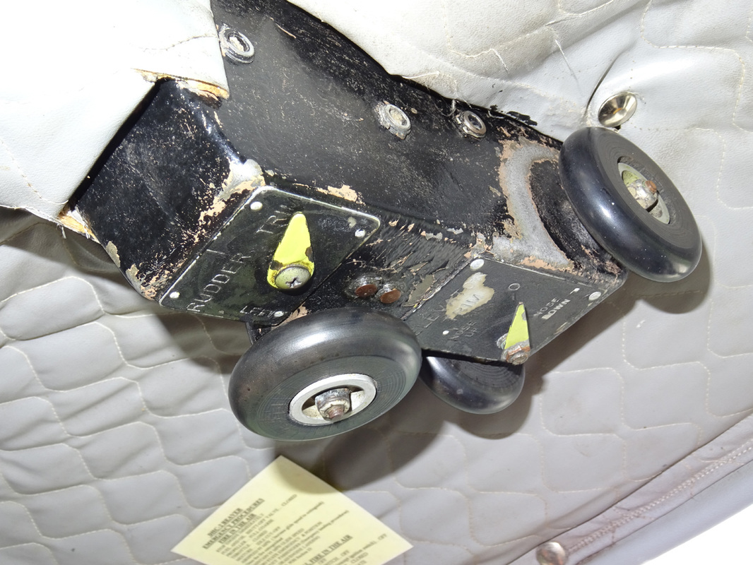
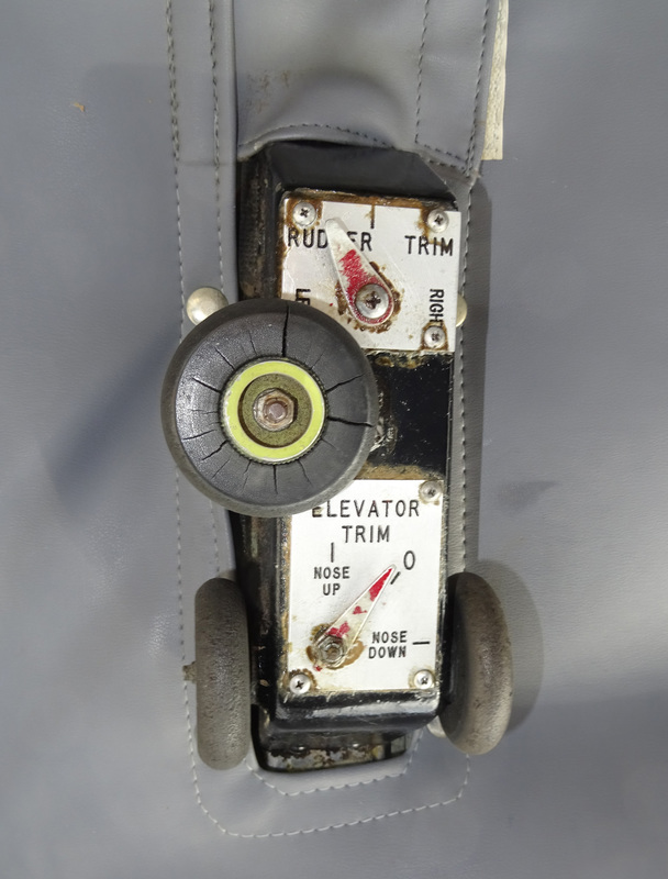
The elevator trim is adjusted by twin handwheels on the cockpit roof, operating in the natural sense. A pointer and scale, between the handwheels, marked NOSE UP, NOSE DOWN, indicate the direction and degree of trim applied.
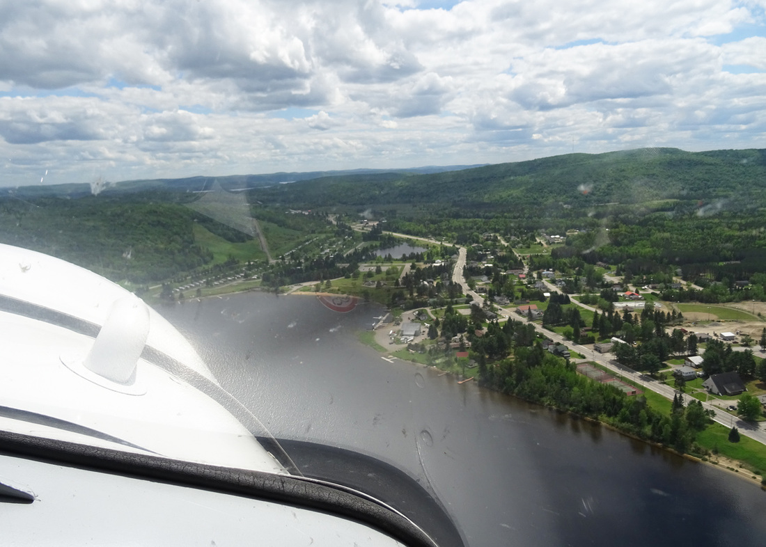
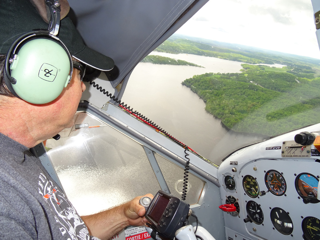
It was smooth ride and far too soon Lac Tiberiade became insight. Before landing on the lake, Eric did an aerial surveillance of the area checking for obstructions such as floating logs or rocks close to the surface of the water. Wind direction must also be taken into account. Different techniques are required for on-shore winds than would be sued for off-shore winds. Flaps were lowered and the approach began.
A view of two operational Piston Otter floatplanes is an amazing sight both on the ground and from the air.
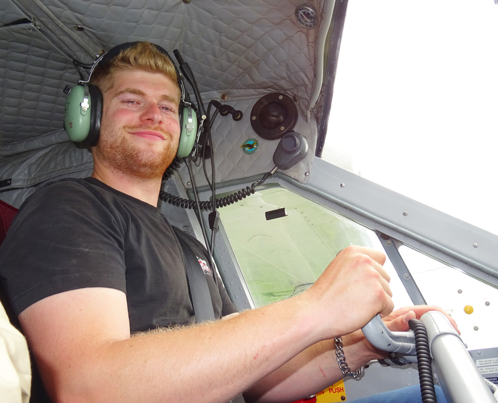
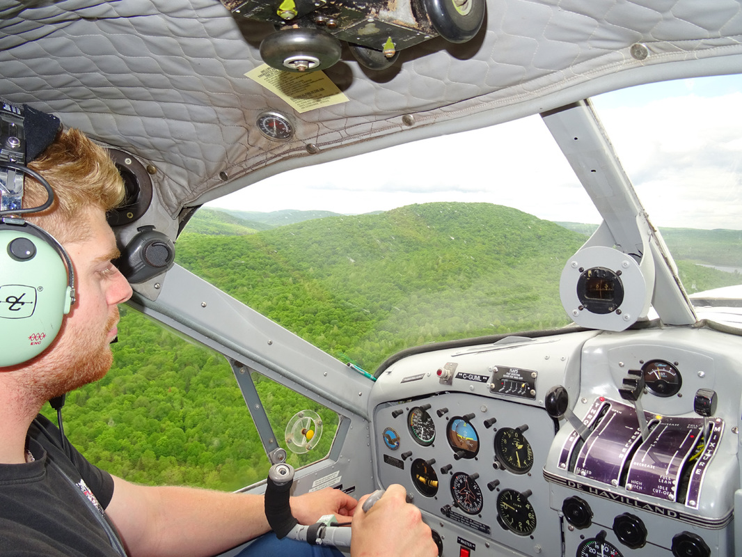
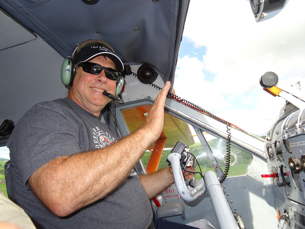
Beaver driver Eric Pelletier with 1.000hrs on DHC-2 did an excellent job of showing me around 'his Beaver'.
I thanked Eric for the interesting trip and his expert commentary on the area. It was an amazing experience at a truly magical and picturesque location. I then retired to a lunch room in the village where I relaxed over lunch and a few beers, reflecting on what had been a truly memorable day.
After the pleasant lunch, the 6-banger fired right away and I set course to Saint-Anne-du-Lac
which is located on the banks of Lac Tapani.
which is located on the banks of Lac Tapani.
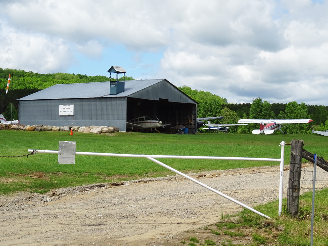
Saint-Anne-du-Lac
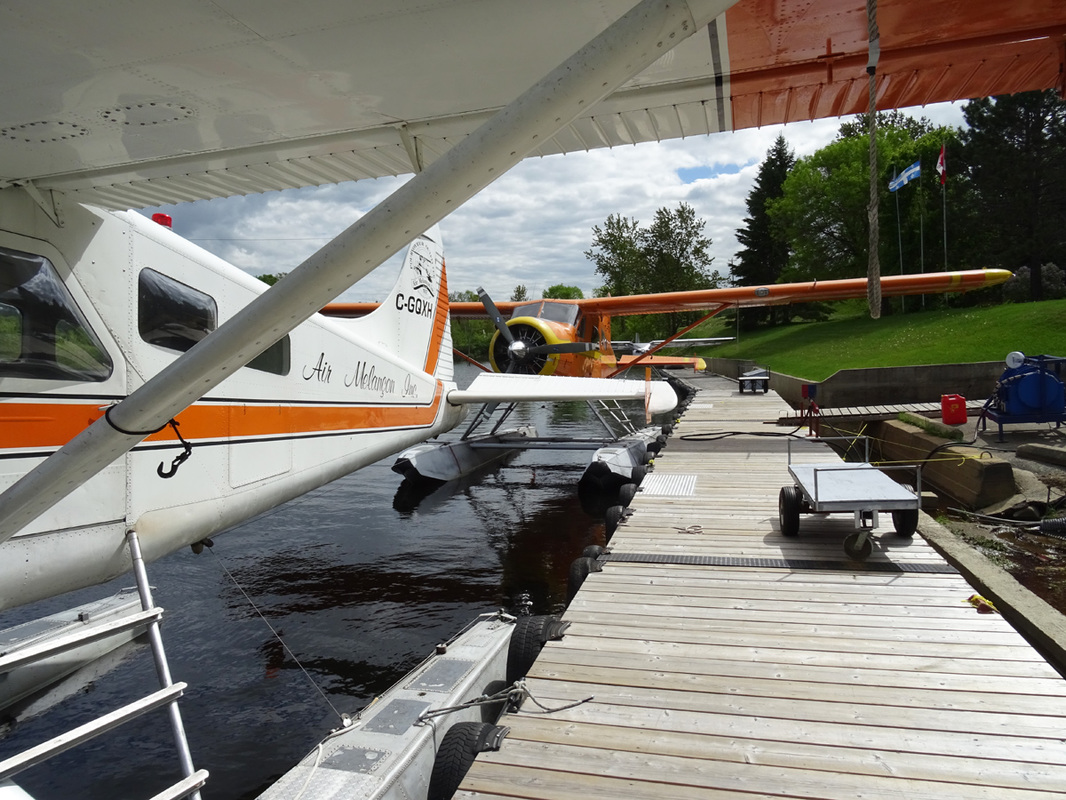
The waterfront scene at Air Melançon at Lac Tapani, Quebec.
Geoffrey de Havilland
The De Havilland Aircraft Company was a British aviation manufacturer founded in 1920 of which Geoffrey de Havilland had been chief designer. He proposed the continuing to name the DHC line of aircraft after Canadian mammals.
In September, 1946, de Havilland put together a design team. The new aircraft was specifically designed to be all-metal, unlike older designs like the famous Noorduyn Norseman, using steel from the engine to the firewall, heavy aluminum truss frames with panels and doors throughout the front seat area, lighter trusses toward the rear and all monocoque construction aft. At the time de Havilland Canada was still a British company and there were plans to fit the evolving design with a British engine. This limited power, so the wing area was greatly increased in order to maintain STOL performance. When Pratt & Whitney Canada offered to supply war-surplus 450 hp (340 kW) Wasp Jr. engines at a low price, the aircraft ended up with extra power as well as the original long wing. The result was unbeatable STOL performance for an aircraft of its size.
In September, 1946, de Havilland put together a design team. The new aircraft was specifically designed to be all-metal, unlike older designs like the famous Noorduyn Norseman, using steel from the engine to the firewall, heavy aluminum truss frames with panels and doors throughout the front seat area, lighter trusses toward the rear and all monocoque construction aft. At the time de Havilland Canada was still a British company and there were plans to fit the evolving design with a British engine. This limited power, so the wing area was greatly increased in order to maintain STOL performance. When Pratt & Whitney Canada offered to supply war-surplus 450 hp (340 kW) Wasp Jr. engines at a low price, the aircraft ended up with extra power as well as the original long wing. The result was unbeatable STOL performance for an aircraft of its size.
|
Watch the show!
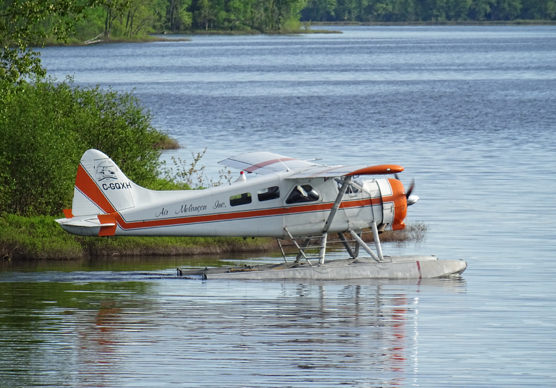
Built in 1953. Classic DHC-2 Beaver C-GQXH, just getting airborne, as it roars passed my location, on its way for a drop-off at an outpost camp. Enjoy |
|
Beaver drivers at rest
|
The moose (North America), is the largest extant species in the deer family. Moose typically inhabit boreal forests and temperate broadleaf and mixed forests of the Northern Hemisphere in temperate to subarctic climates. Hunting and other human activities have caused a reduction in the size of the moose's range over time. Moose have been reintroduced to some of their former habitats. Currently, most moose are found in Canada, Alaska and Russia. Their diet consists of both terrestrial and aquatic vegetation. The most common moose predators are the gray wolf along with bears and humans. Unlike most other deer species, moose are solitary animals and do not form herds. Although generally slow-moving and sedentary, moose can become aggressive and move quickly if angered or startled. Their mating season in the autumn features energetic fights between males competing for a female.
|
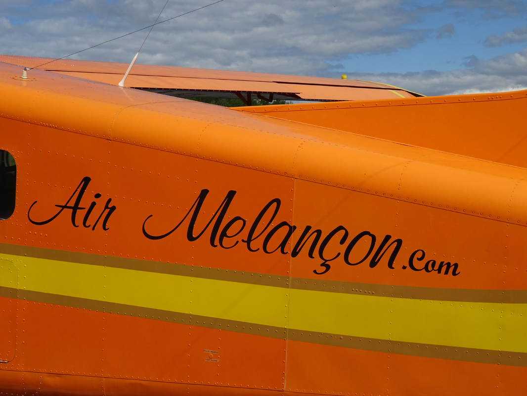
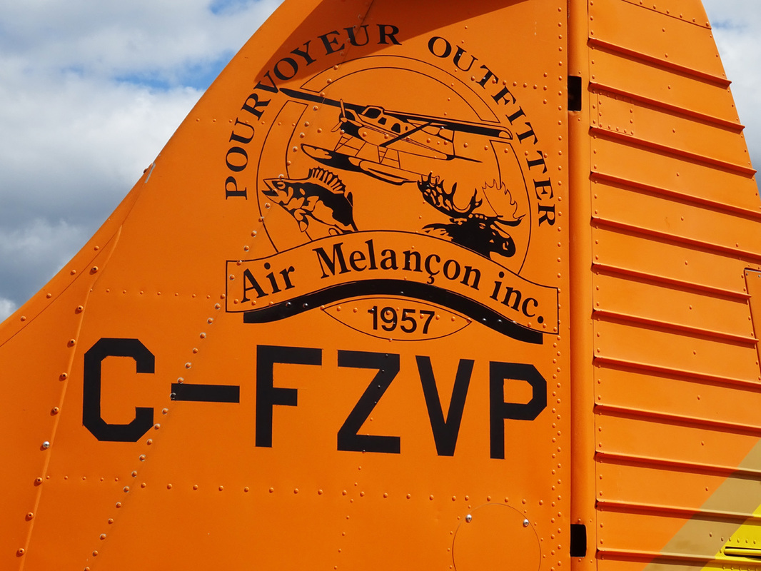
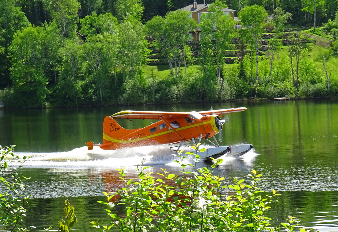
Air Melançon’s Beaver C-FZVP, manufactured in 1957 with construction number 1033, was acquired by the Melançon's in 1989. This De Havilland DHC-2 Beaver started her career working in Libya, North-Africa, with the Oasis Oil Company. When her African adventure was over she returned to Canada in May 1971 and passed through the hands of bush-plane operators like; Ste Agathe Air Service and Tamarac Air Services. At some point she became part of Air Mont Laurier fleet in 1982 and still is serving this Ste Véronique, Quebec, based operater every day.
C-FZVP is seen here step taxiing down Lake Tapani on this gorgeous spring morning.
|
Fuel is contained in three tanks under the cabin floor which are used separately. They are serviced through three filler necks in a filler compartment protected by a hinged door on the forward left-hand side of the fuselage, adjacent to the cockpit door. For long range operation non-jettisonable wing tip tanks may be installed to replace conventional wing tips. Fuel from these tanks is gravity fed to the front tank.
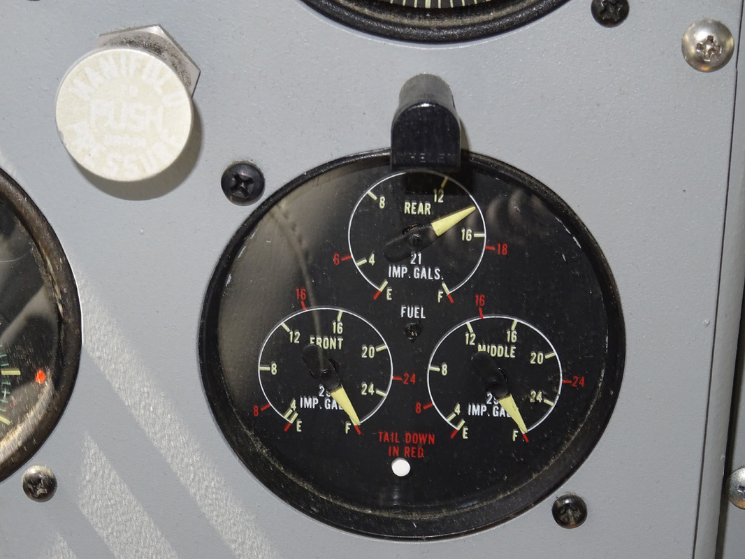
The fuel transfer selector, for use when wing tip tanks are installed, is located to the left of the pilot, above the cockpit door window. It has four positions marked LH, RH, BOTH and OFF. A fuel wobble pump lever, below the engine instrument panel on the pedestal, is used to build up the fuel pressure to 5 psi, for starting the engine. The emergency shut-off lever, on the right side of the pedestal, below the engine instrument panel, is normally wirelocked in the down position. When pulled sharply up to break the wire lock and moved to the closed position, it cuts off the supply of both fuel and oil to the engine. A triple indicator fuel contents gauge, located on the right side of the engine instrument panel, is graduated in Imperial gallons, in white and red figures for in-flight and tail down positions respectively. A combined fuel pressure, oil pressure and oil temperature gauge is located on the left side of the engine instrument panel. On some aircraft a red warning light, which lights up when the fuel pressure drops to 3 psi, is positioned above the flight instrument panel. The engine is started either by an electrical direct cranking starter motor. The starter switch for the electrical direct cranking starter motor and the starter clutch and boost coil switches require for the electrical inertia starter are located on the starter panel below the flight instrument panel. Conventional engine instruments are mounted on a panel below the engine controls quadrant on the pedestal. The engine instruments consist of: Tachometer, Manifold Pressure Gauge, Cylinder Head Temperature Gauge, Carburetor Mixture Temperature Gauge, combined Oil and Fuel Pressure and Oil Temperature Gauge. The starter Brush Release Socket is also located on the engine instrument panel. The engine drives a Hamilton-Standard two-bladed 8 ft. 6 inches diameter constant speed, counterweight type propeller having a pitch range for 11.5 to 24 degrees. |
|
|
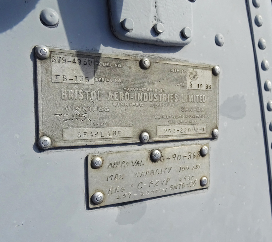
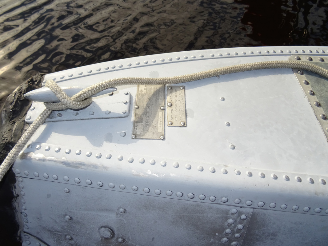
Bristol Aerospace began in 1930 as the MacDonald Brothers Aircraft Company.
Brothers Jim and Grant MacDonald moved to Winnipeg from Nova Scotia in 1904 to start a sheet metal business. Brother Edwin joined them later and by the late 1920s air travel had become an important means of transportation with Winnipeg becoming a hub for travel to the booming west. The MacDonalds formed MacDonald Brothers Aircraft Company in 1930, producing seaplane floats under licence from EDO. The company produced floats into the early 1980s. |
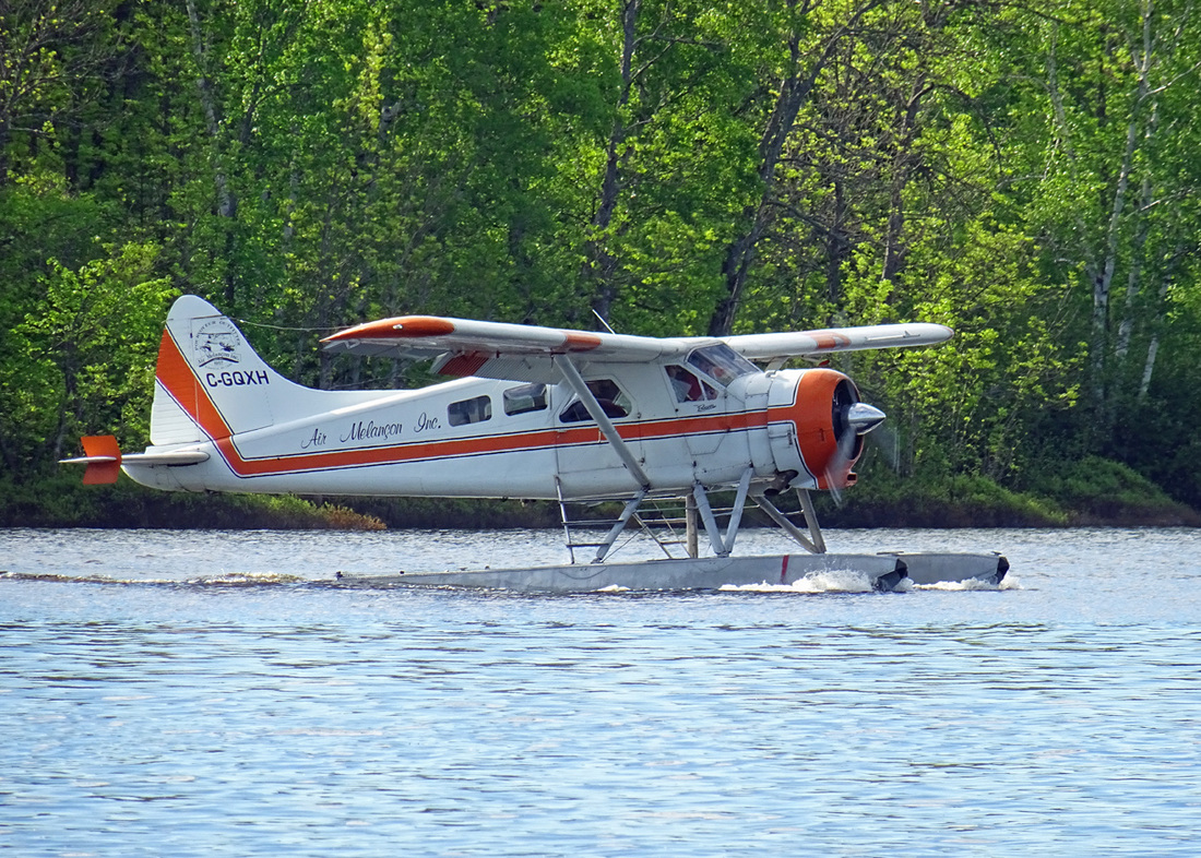
C-GQXH is warming-up her Pratt & Whitney on the calm waters of Lake Tapani.
Description of the De Havilland DHC-2 Beaver Normal Flight Procedures as describe in the Flight Manual of 1957
Engine warm-up:
Throttle to give 1000 rpm.Move propeller lever fully forward to INCREASE RPM, as soon as oil pressure reaches 50 psi.
After oil temperature has reached 40 degrees Celsius (100 dgr. F), adjust to smoothest engine speed between 1000 to 1400 rpm. Mixture lever FULL RICH.
Select propeller lever to coarser pitch at 1000 rpm, to circulate the oil in the constant speed unit and propeller cylinder. Then return to INCREASE RPM.
Never rush engine warm-up.
Check oil pressure, fuel pressure and temperature.
Tank feeds – check by rotating fuel selector to each tank.
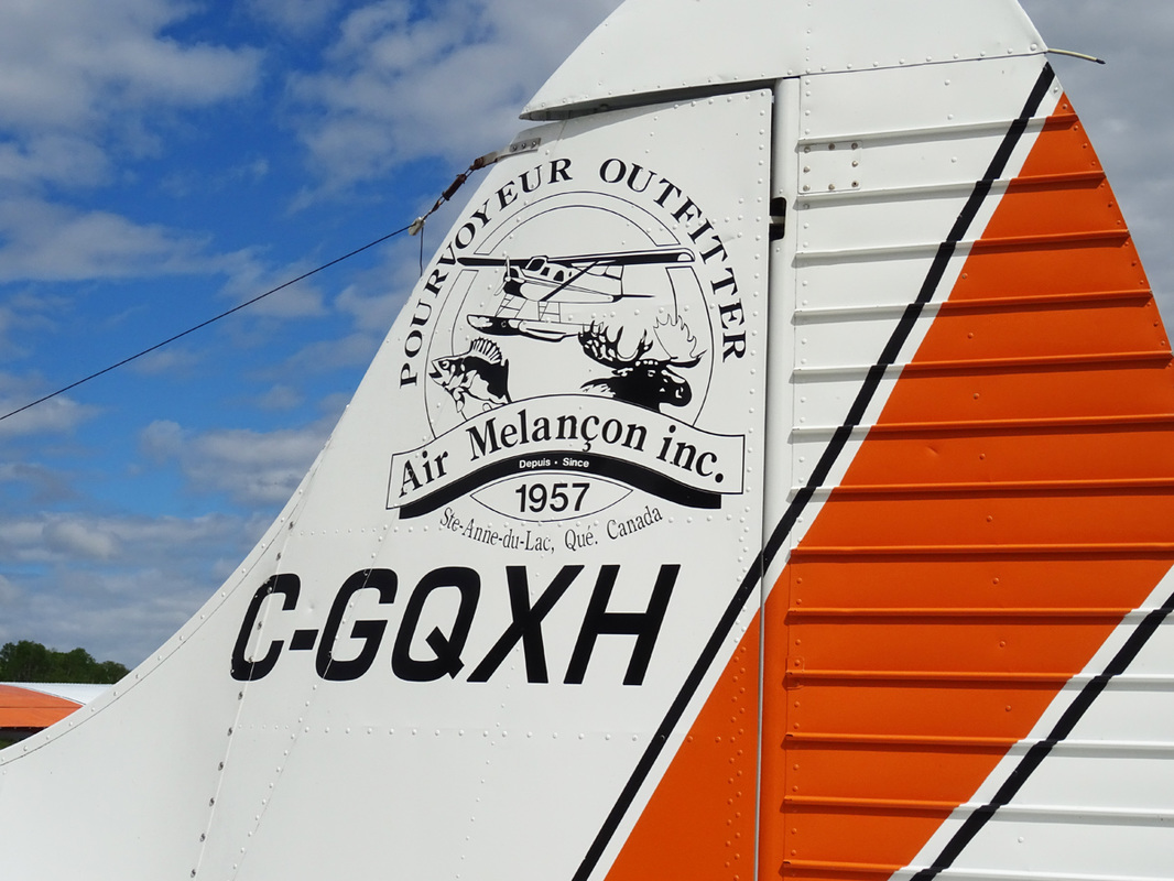
C-GQXH started its career with delivery in 1953 to the USAF in both the U.S. and Germany. After her military career with the USAF was over, she was stored for some months at Davis Monthan AFB in Arizona until October 1965 before passed to Maryland ANG, who disposed the Beaver in the mid '70s. After a career with several operators in the US, the Beaver was exported back to Canada in 1980 and was registered as C-GQXH Air Melançon of Ste., Anne du Lac, Quebec in July 1980.
Air Melançon DHC-2 Beaver C-GQXH is being fueled for her second flight of the day at the dock on Lake Tapani.
Three-Blade Propeller. Due to its shorter diameter, the three-blade propeller is smoother, quieter and less subject to blade damage than a two-blade propeller. There's also a weight saving of 56-61 pounds and a cost saving of up to 50 percent at overhaul time.
|
A shock-mounted flight instrument panel is provided for the pilot and incorporates and altimeter, turn-and-bank indicator, rate-of-climb indicator, air speed indicator, directional gyro and artificial horizon. The airspeed indicator, altimeter and the rate-of-climb indicator, are operated by the pitot static system, The static opening is incorporated in the left-hand side of the rear fuselage. The directional gyro, artificial horizon and turn-and-bank indicator, are operated by the vacuum system. A vacuum gauge on the right of the electrical switch panel indicates the vacuum in In.Hg. being applied to the instruments.
The outside air temperature gauge is located in the cockpit roof. It is of the direct-reading bulb type and the dial is graduated in both Fahrenheit and Centigrade scales. The artificial horizon is powered by the vacuum system. Its horizon bar gives a dive, climb and angle of bank indication. A knob at the bottom of the instrument dial permits adjustment of the instrument to any fore-and-aft attitude of the airplane within limits of plus or minus 7 degrees Celsius. A caging knob on the instrument erects the gyro and locks the horizon bar in the horizontal position. This knob must be in the uncaged position before take-off to insure proper indications from the instrument. The operating limits are set to permit 70 degrees climbs and glides and 100 degrees right or left banks before the limit stops are reached. If exceeded, the caging knob provides a rapid means for resetting the artificial horizon. The magnetic compass is mounted on a bracket attached to the windshield center post. The switch for the compass light is on the electric switch panel. A compass deviation card is mounted above the compass. Hot air for heating the interior of the cabin is supplied by ram air passing through a heat exchanger tube in the engine exhaust system. From a four-way outlet at the center of the cockpit floor, the heated air is ducted to the pilot’s seat and front passengers feet and to two outlet grills in the cabin floor. A heated air outlet at the top of the instrument panel permits defrosting of the pilot’s windshield. All hot air outlets are controlled simultaneously by a push-pull control, on the base of the pedestal which permits intermediate positions between ON in its up position and fully OFF. Two ventilation louvers, one on each side of the cockpit roof, to the left and right of the pilot and co-pilot, supply ram air to the cabin from screened openings in the leading edge of each wing root. The ventilation louvers are adjustable. They open when the knob, on the side of the louver, is turned clockwise. Intermediate positions between OPEN and SHUT are possible. To control the direction of airflow from the louver, its body can be moved to point in any required direction. An exhaust type circular grill and shutter ventilator in the cabin roof exhausts air from the cabin. Necessary suction is provided by a rearward facing air scoop on top of the fuselage. A fuel wobble pump lever, below the engine instrument panel on the pedestal, is used to build up the fuel pressure to 5 psi, for starting the engine. The emergency shut-off lever, on the right side of the pedestal, below the engine instrument panel, is normally wirelocked in the down position. When pulled sharply up to break the wire lock and moved to the closed position, it cuts off the supply of both fuel and oil to the engine. The oil tank is located aft of the fire-wall and is serviced from inside the cockpit through a filler at the base of the pedestal. The capacity is 5 ¼ imperial gallons. |
|
The wing flaps are of the slotted type and extend from the wing roots to the inboard ends of the ailerons which also droop in conjunction with the flap movements. The flaps are operated by an actuating cylinder located in the fuselage at the left-hand wing root. Hydraulic fluid is supplied to the actuating cylinder by a handpump, under the pilot’s seat. This handpump has an integral reservoir, a selector valve and a relief valve. The relief valve is set at 1,000 psi.
The wing flap hand pump lever is at the right-hand side of the pilot’s seat and is operated in a fore-and-aft direction.
The wing flaps selector lever is located on the right-hand side of the pilot’s seat. It has two marked positions, UP and DOWN. Intermediate positions of the wing flaps are selected by moving the selector lever to UP or DOWN then pumping the wing flaps with the hand pump lever to the desired position, as shown on the wing flaps indicator. If the flaps are in any lowered position, it is essential that the selector lever is retained in the DOWN position. When the flaps are retracted, the selector lever must be retained in the UP position. Once the selector lever is set to DOWN and the flaps are pumped to the desired position, the selector lever must not be moved until it is desired to change the flap position.
A wing flaps position indicator is situated above the flight instrument panel. It is marked FULL FLAP, LANDING, TAKE-OFF, CLIMB and CRUISE. FULL FLAP is only required for emergency landing in very restricted areas.
|
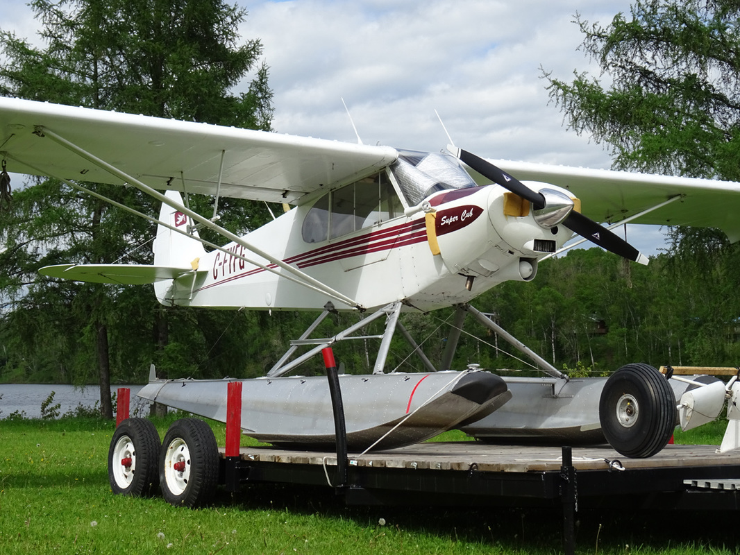
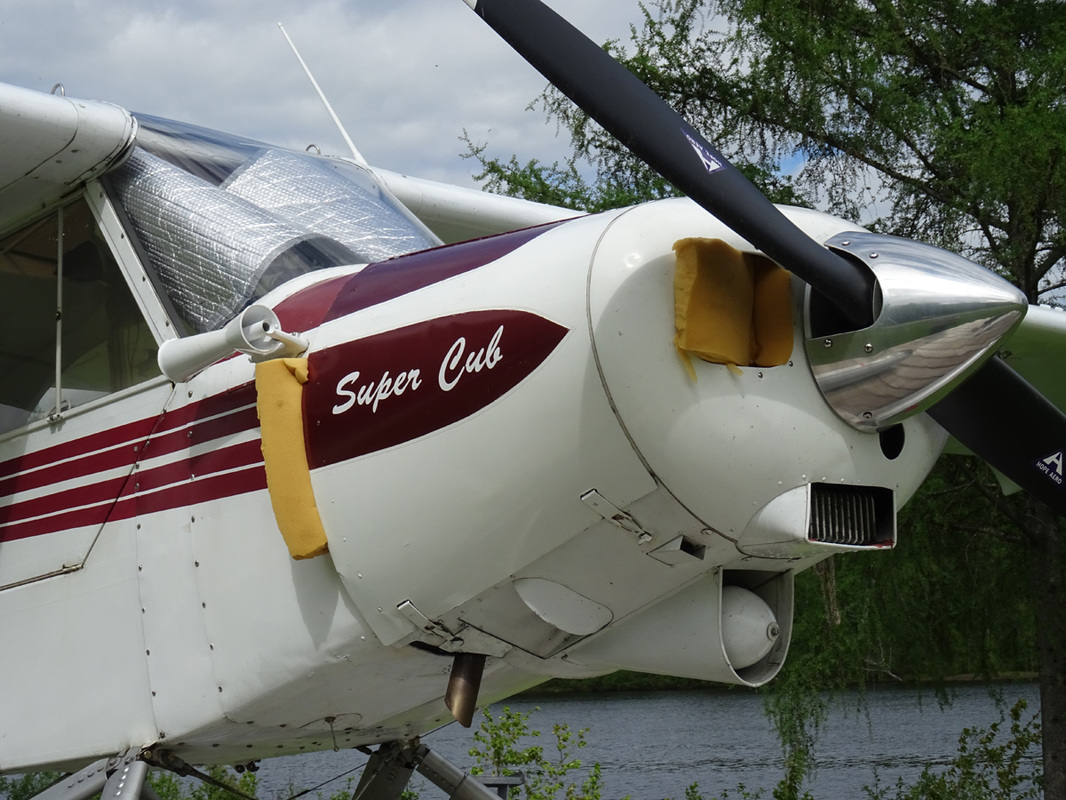
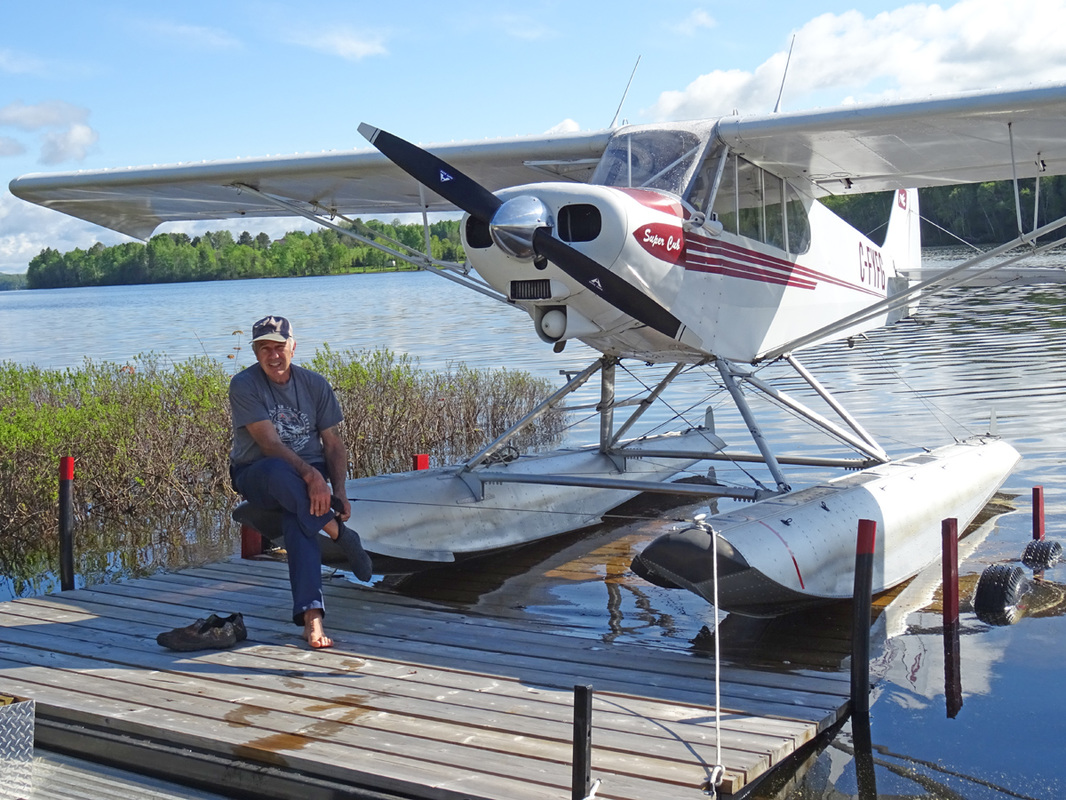
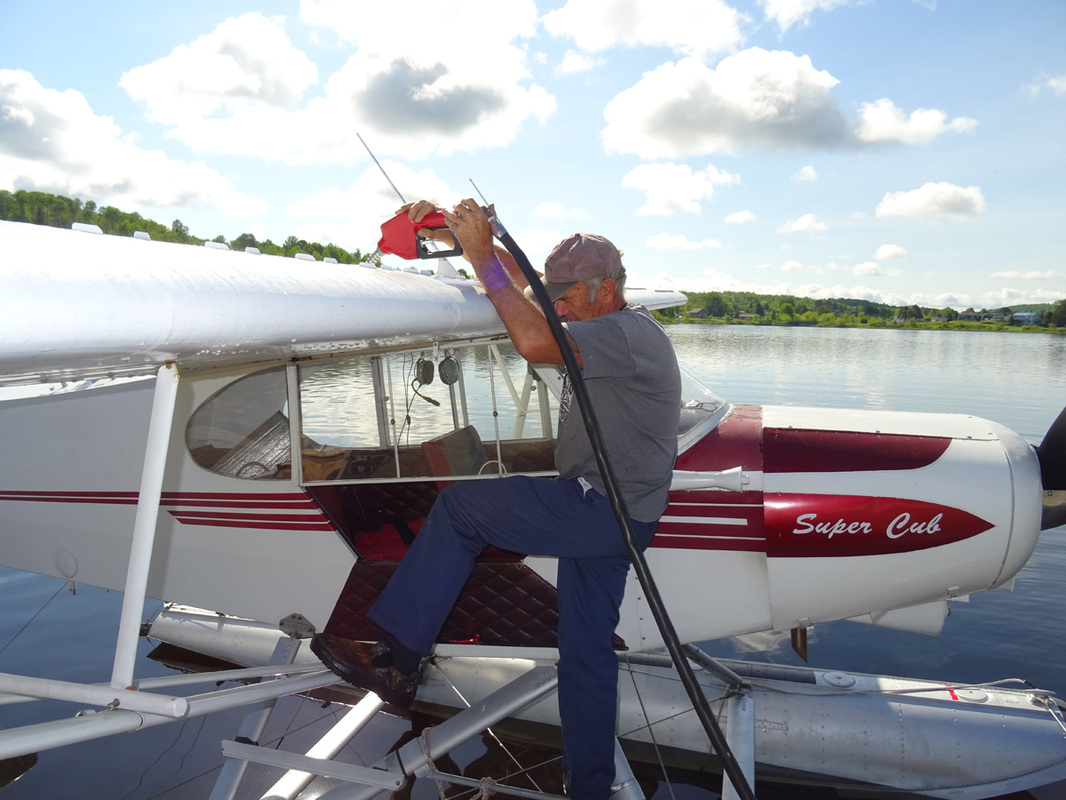
C-FYFG is a 1969 built Piper PA-18-150 Super Cub.
The Piper PA-18 Super Cub is a two-seat, single-engine monoplane. Introduced in 1949 by Piper Aircraft, it was developed from the Piper PA-11, and traces its lineage back through the J-3 to the Taylor E-2 Cub of the 1930s. In close to 40 years of production, over 9,000 were built. Super Cubs are commonly found in roles such as bush flying, banner and glider towing. |
|
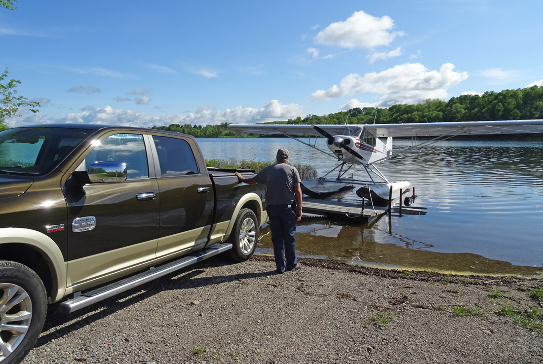
In the early morning I found a Super Cub on floats on a trailer on the Air Melancon parking place. Gary Melancon appeared to be the driver.
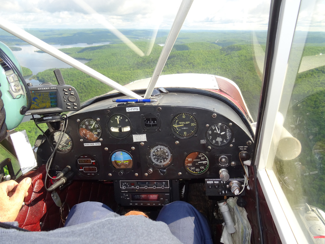
I had met Gary the day before, while unloading the company Beavers. When we inquired about the Super Cub, C-FYFG, Gary said it changed wheel for floats and needed at test-flight to see if everything is OK. He asked me if I would like to fly up with him. I immediately consented. First we had to launch the Super Cub into the river, which was a relative easy job to do. With Gary behind the controls, C-FYFG thundered across the water on its take off run and in seconds the venerable Super Cub was airborne. Gary is a very kind person and a very experienced bush plane driver with a total of 10,000+ flying hours in all kind of bush planes. Visibility was excellent and we could see fishing boats on the dark green lake, with island capped with pine trees. |
Gary is a very kind person and a very experienced bush plane driver with thousands of flying hours in all kind of bush planes.
|
While based on the design of the earlier Cubs, the addition of an electrical system, flaps (3 notches), and a considerably more powerful engine (150 hp), make it a very different flying experience. Although the "standard" Super Cub was fitted with a 150-horsepower (112 kW) Lycoming engine, it is not uncommon to see them equipped with a 160-horsepower O-320-B2B, or even 180 horsepower (134 kW) Lycoming O-360 powerplant.
The high-lift wing and powerful engine made the Super Cub a prime candidate for conversion to either floatplane or skiplane. In addition, the PA-18A (an agricultural version) was produced for applying either dry chemical or liquid spray. |
Visibility was excellent and we could see fishing boats on the dark green lake, with island capped with pine trees.
|
The floats gently brushed the water with a ‘splash’ The floats gently brushed the water with a ‘splash’ and the aircraft decelerated. Gary taxied the Piper towards the jetty and shut down the engine to let the floatplane gently drift in the water. This is the moment where the judgment of the pilot is essential, if the dock is approached too fast there is the danger of a collision and damage to both aircraft and dock. Too slow and the aircraft will not reach the dock, thereby causing some embarrassment to the pilot! The Piper came to rest and the mooring ropes were secured to the tie-down points. The Gary opened the cabin door to allow us to disembark onto the dock. Our flight time had been a mere 35 minutes.
|
This must be one of the world's most picturesque water aerodrome - especially on a clear morning like this
|
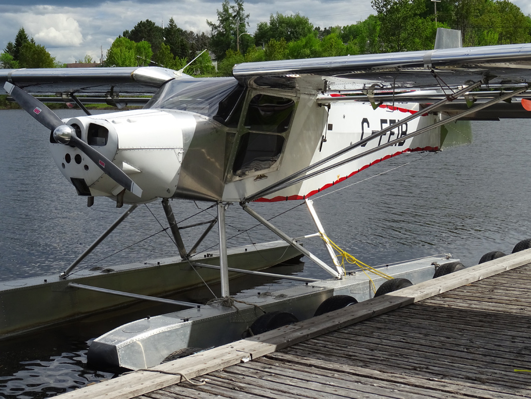
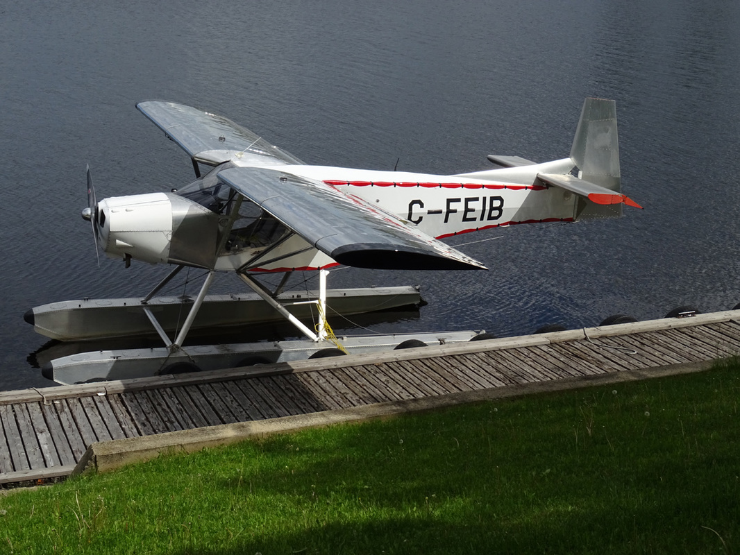
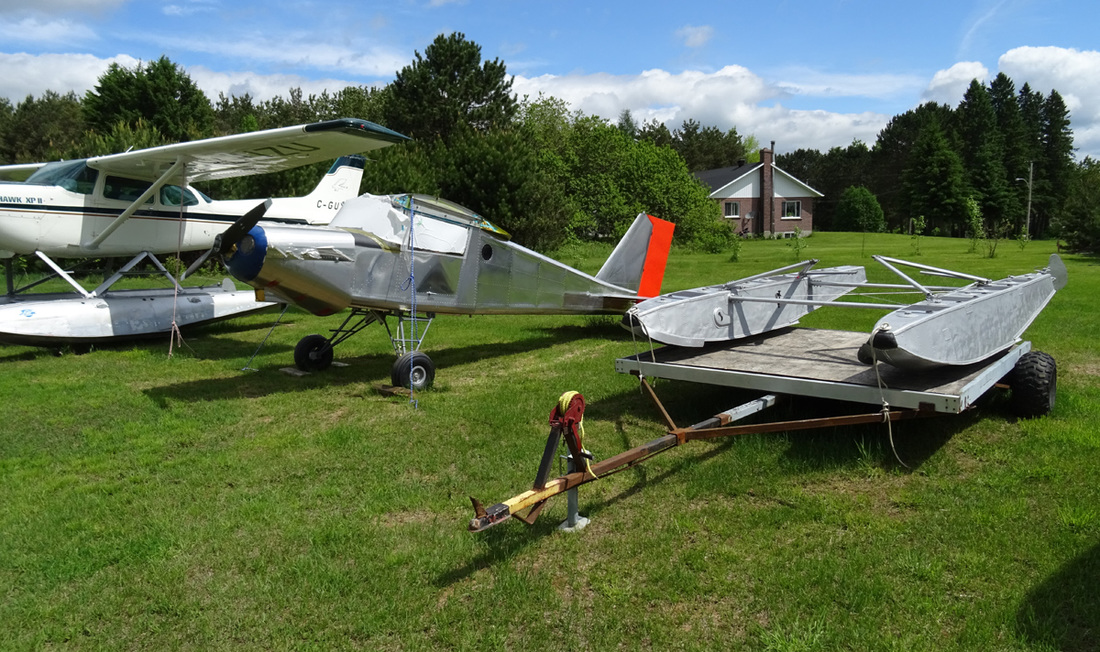
C-FEIB is a 2005 built Pegazair 100.
The Pegazair-100 STOL is a two-seat STOL homebuilt aircraft developed in Canada by Tapanee Aviation, Inc. of Mont-Saint-Michel, Quebec. Development of the Pegazair started in 1985 by Serg Dufour of Mont-Saint-Michel, Quebec. Originally it consisted of a new set of Pega-STOL wings with retractable leading edge slats to be installed on Zenair CH 701 STOLs to replace their wings which have fixed leading edge slots. Dufour went on to develop a new fuselage and tail to match the wings. The Pegazair is a two seats in side-by-side configuration, strut-braced, high-wing monoplane with conventional landing gear. Fuselage construction is welded steel tubing with aluminum skin. The wings employ full length flaperons and leading edge slats that deploy automatically. The tailplane is slotted for slow speed authority. The prototype was outfitted with a 65 hp (48 kW) Continental A-65 engine. |
|
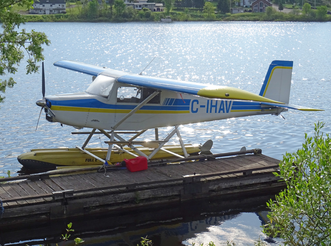
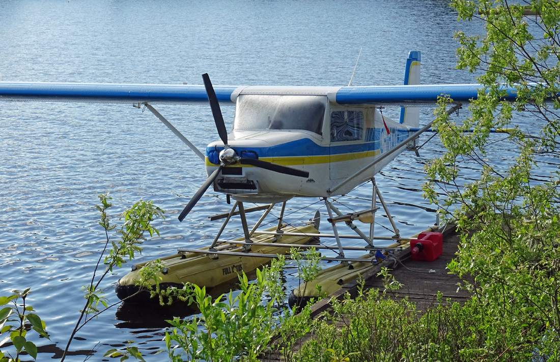
C-IHAV, seen here at Saint-Anne-du-Lac airstrip, is a 2001 built Murphy Rebel sitting on top of Full Lotus floats.
The Murphy Rebel is a two- or three-seat, strut braced, high wing, taildragger monoplane which is sold in kit form by Murphy Aircraft in Chilliwack, British Columbia, Canada. The Rebel was designed by Murphy Aircraft President Darryl Murphy and Dick Hiscock, who was one of the designers of the De Havilland Canada DHC-2 Beaver. The Rebel is a STOL aircraft and was designed to be a personal-use bush plane. It can operate from short, unimproved airstrips and can carry a useful load of up to 750 lbs. The aircraft features a strut-braced high-wing, a two or three seat enclosed cabin accesses via doors, fixed conventional landing gear and a single engine in tractor configuration. The aircraft is made from sheet aluminum. The recommended engine for the Rebel is the 160 hp (120 kW) Lycoming O-320. |
Open the door, hop in and lets go flying!
Beaver driver Gilles Roothier who has 10.000 hrs on the Beaver is still enjoying his job everyday!
- How does it works? -
Gilles was so kind to explain the start up procedures and flying characteristics of the Beaver to me.
“ To start De Havilland Beaver with the Pratt & Whitney R-985 motor, you start with using the primer, which is located just by the doorway. Use approximately 4 to 5 strokes of the primer and put the mixture lever to rich. Master switch on and then you engage the starter switch. Count 1, 2, 3, 4, 5 blades and then turn the mags on. With a little noise and smoke it should start! Left of the mixture levers is the throttle and on the left side is the prop-lever. When you start it up, you must make sure to have 40 degrees Celsius of oil temperature as warming up is the most critical part of the 985 radial air-cooled engine “.
“Which flap settings does one have to use on the Beaver?”
“The flap settings we use in most cases, in both landing and take-off, is the take take-off setting. The flaps are selected by use of the selection valve and is moved using a hydraulic pump with a little arm at the right side of the pilot. The flap indicator moves down to the take-off position and if you look out the window, you will see both flaps and ailerons come down. We have slotted ailerons for more lift on take-off “.
“What are the mandatory power settings?”
“Only for taxiing around, I use about 600 to 700 RPMs. For the take-off you will set 36½ inches manifold pressure and that will give approximately 2300 RPM. The initial power reduction for normal climb is back to 30 inches MP and 2000 RPM. For cruising we use 28 inches and 1800 RPM. In the pattern, before landing, I bring the power to 20 inches or less and bring the propeller back as well to 1700 RPM to smooth her out. You select the carbkey to hot to eliminate any icing in the carburetor. Do your pattern around a 105 miles per hour, which is your flap speed. As you turn the base, start putting flap down for approach at 80 and touch down at 70 to 65 miles per hour “.
“What kind of fuel does one need for the Beaver?”
“For this particular plane we use 100 low lead. We are certified to use Mo-gas, as we use to call it, which has a minimum of 80 to 87 octane’s. We have three tanks in the aircraft. The front-, middle or center- and rear tank. They each carry 29, 29 and 21, with a total of 79 imperial gallons. We burn about 20 imperial gallons per hour. The AV-gas is a CAN 2.10 the liter.
An interesting thing about the De Havilland Beaver is its oil-reservoir. Even with the engine running you can check or add oil if you want as the filling cap is situated on the right side of the instrument console “.
“What about communications and navigations?”
“Look out the window! It’s strictly VFR. We do have a GPS on the Beaver because it’s a handy and inexpensive navigation aid. There’s no ATC control. We use the broadcast philosophy. Just before take-off and landing we broadcast our intentions on the local frequency and people in the air know there’s conflicting traffic “.
“What is the difference between a Beaver landing on wheels and floats?”
“Float landings are generally a flatter approach and you are not looking for an aiming point, as just a smooth touchdown in smooth water. As on a defined runway you pitch the hatch mark for touchdown point and do that “.
“How does one steer a Beaver on floats?”
“For steering you use the rudders. The foot pedals are connected to both the air-rudders and water-rudders. Before you take-off you pull the water rudder up, using the water pull-up cable retracted in up position for flight. Keep in mind, on the water there are no brakes! You have to make sure that you have enough room to maneuver. It’s a fluid medium so you can’t stop or do hard turns, it all depends on the wind and tide”.
“What do you like most of the Beaver?”
“It’s a marvelous airplane for our type of flying. Low level, low speed and even when the visibility is poor you can slow it down to 80 miles per hour and still maneuver quite well”.
Flying Time !
“Strap in and enjoy the ride ”. Gilles passed out earplugs instead of peanuts but I refused. I wanted to enjoy the full roar of the Pratt & Whitney R-985 radial engine.
Start-up, followed by a short taxi and off we went !
The Saint-Lawrence River flows in a glacier carved valley, of which the Laurentian mountains are the natural granitic shield, covered with thousands of square miles of green forests and blue lakes.
Beaver driver Gilles Roothier brings Air Melançon DHC-2 Beaver C-FZVP in for a fine landing on Lac Tapani in the Province of Quebec.
After arrival back at the base, I absorbed the beauty of the setting for a moment longer. Finally, it was time to leave. I thanked the AIR MELANÇON staff for their kind hospitality, left the dock and made my way to a coffee shop for coffee and muffins.
Anne-du-Lac airfield
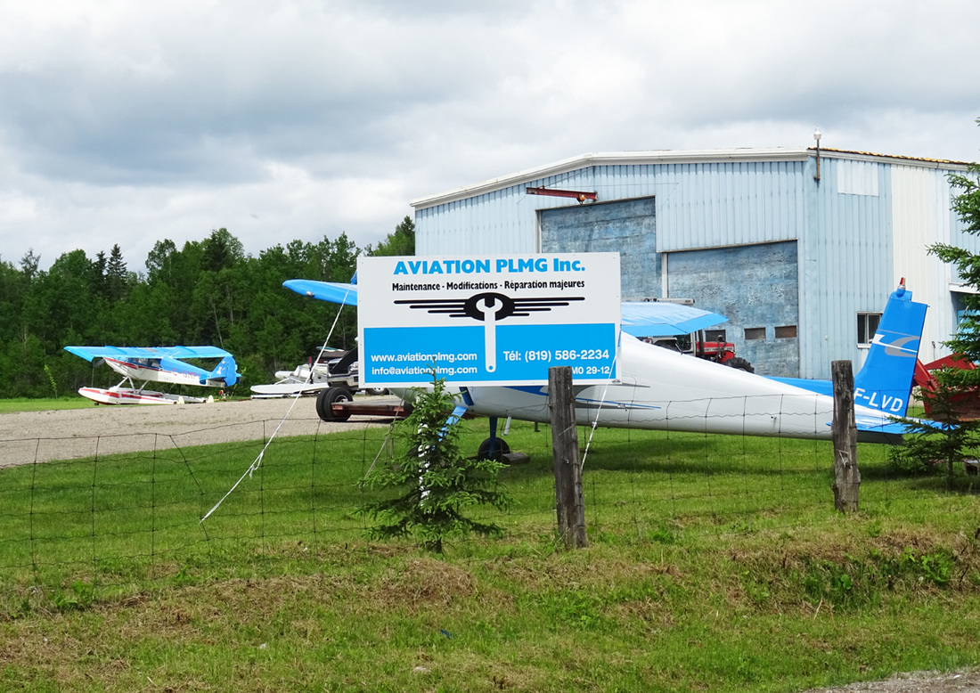
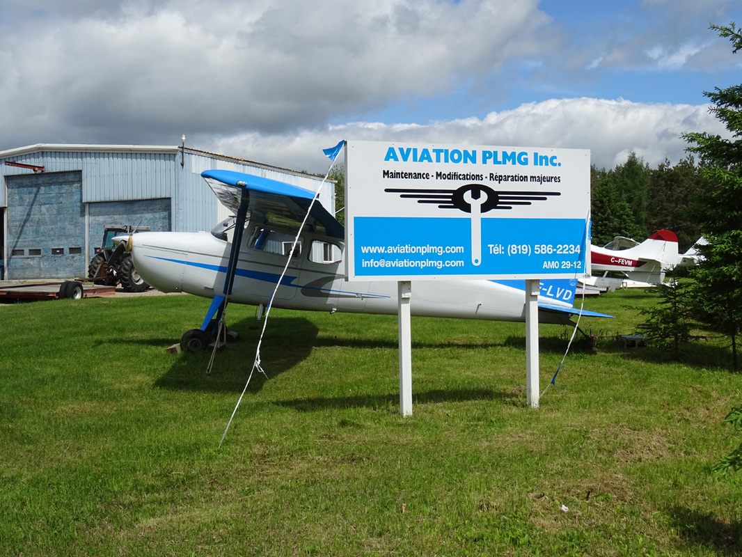
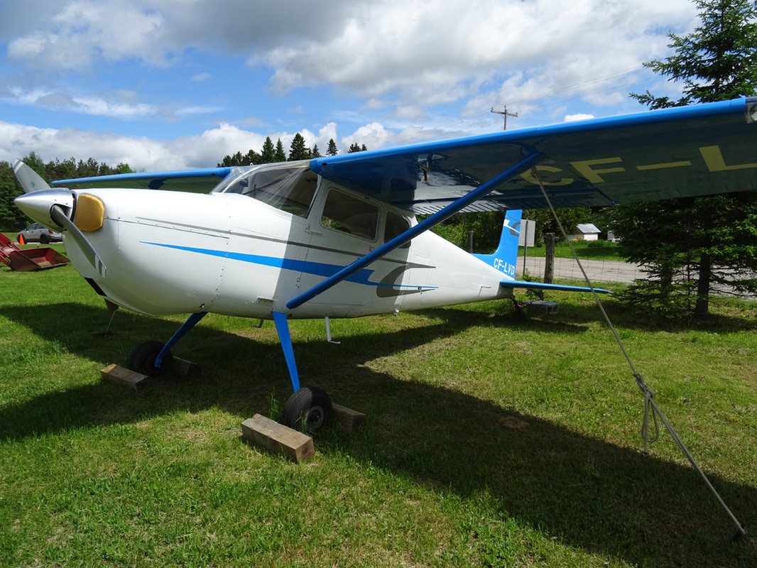
CF-LVD is a very, .... very old Cessna 172. This one was built in 1957!
The Cessna 172 Skyhawk is a four-seat, single-engine, high wing, fixed-wing aircraft made by the Cessna Aircraft Company. First flown in 1955, more Cessna 172s have been built than any other aircraft.
Measured by its longevity and popularity, the Cessna 172 is the most successful aircraft in history. Cessna delivered the first production models in 1956. As of 2015, Cessna, and its partners, had built more than 43,000.
The Cessna 172 started life as a tricycle landing gear variant of the taildragger Cessna 170, with a basic level of standard equipment. In January 1955, Cessna flew an improved variant of the Cessna 170, a Continental O-300-A-powered Cessna 170C with larger elevators and a more angular tailfin. Although the variant was tested and certified, Cessna decided to modify it with a tricycle landing gear, and the modified Cessna 170C flew again on 12 June 1955. To reduce the time and cost of certification, the type was added to the Cessna 170 type certificate as the Model 172. Later, the 172 was given its own type certificate, 3A12. The 172 became an overnight sales success, and over 1,400 were built in 1956, its first full year of production.
Early 172s were similar in appearance to the 170s, with the same straight aft fuselage and tall landing gear legs, although the 172 had a straight tailfin while the 170 had a rounded fin and rudder. In 1960, the 172A incorporated revised landing gear and the swept-back tailfin, which is still in use today.
The basic 172 appeared in November 1955 as the 1956 model and remained in production until replaced by the 172A in early 1960. It was equipped with a Continental O-300 145 hp (108 kW) six-cylinder, air-cooled engine and had a maximum gross weight of 2,200 lb (998 kg). Introductory base price was US$8,995 and a total of 4,195 were constructed over the five years.
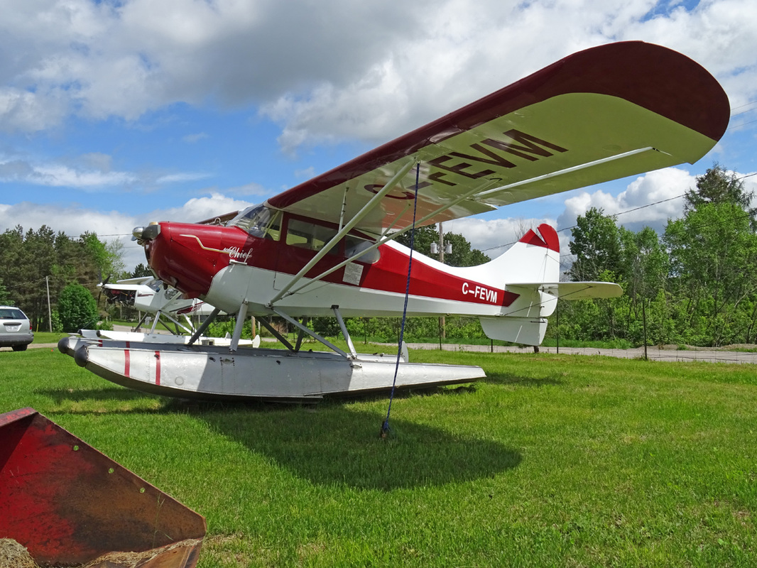
Cool to catch this old girl. Aircraft built in 1947. C-FEVM is a beautiful classic Aeronca Chief.
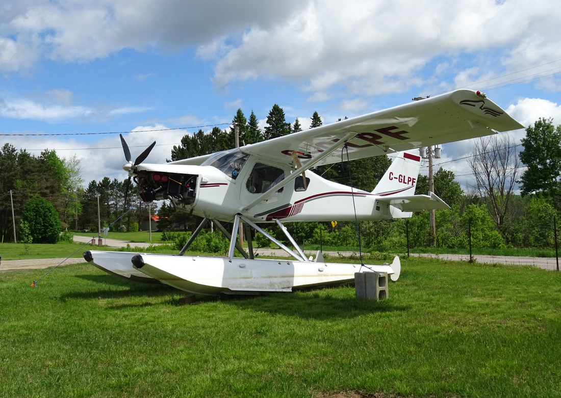
C-GLPF is a 2001 built Ultravia PELICAN P.L.
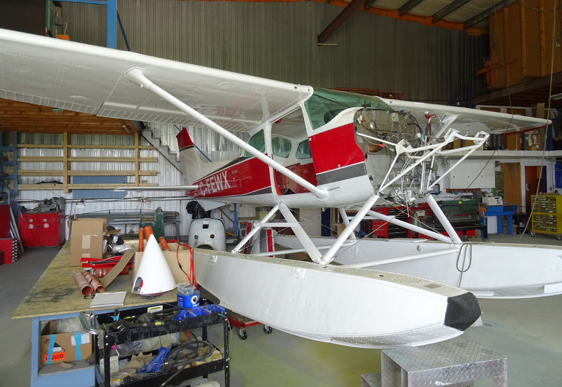
C-FEWX is a Cessna R172K Hawk XP.
The Skyhawk XP (marketingese for Xtra-Performance) introduces higher horsepower and the constant speed propeller to the American 172 market. The XP 195 hp Continental 10-360-K fuel injected engine is actually the well-known 210 hp Continental, but all the muffling required to meet FAA/EPA standards sucked up 15 horses.
The Skyhawk XP (marketingese for Xtra-Performance) introduces higher horsepower and the constant speed propeller to the American 172 market. The XP 195 hp Continental 10-360-K fuel injected engine is actually the well-known 210 hp Continental, but all the muffling required to meet FAA/EPA standards sucked up 15 horses.
Cessna 180 Skywagon: The Pickup Truck of the Air
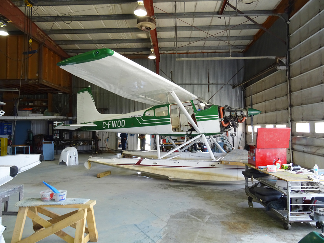
C-FWOO is a 1965 built Cessna 180C. Along with the Super Cub, Cessna 180s and 185s are considered to be prime bush planes. While the Cessnas will not offer the same short field abilities of the Super Cub, they will easily carry four adults. Some models are fitted with six seats but the last two seats are very small and cramped. Like the Super Cub, Cessna 180s and 185s are easily fitted with floats, skis or tundra tires. Cessna ceased producing the 180 in 1981 and the 185 in 1985.
Four seat 180C is powered by a 230 hp (172 kW) Continental O-470-L or O-470-R and was first certified on 8 July 1959.
Among the more significant changes of the 1960 Model 180C were:
Four seat 180C is powered by a 230 hp (172 kW) Continental O-470-L or O-470-R and was first certified on 8 July 1959.
Among the more significant changes of the 1960 Model 180C were:
- Fuel cells changed to inlude flush fuel tank caps on the upper surface of the wings.
- Seat backs made adjustable with optional headrests..
- The airscoop was removed and the airscreen flush-mounted on the front of the cowl.
- New stabilizer-elevator down spring to improve longitudinal stability.
- A redesigned bulkhead and skin on top of fuselage increased headroom in the third and fourth seats.
- O-470-L engine introduced.
The Continental O-470 engine is a family of carbureted six-cylinder, horizontally opposed, air-cooled aircraft engines that was developed especially for use in light aircraft by Continental Motors. When the US military gave them all the designation of O-470 the company adopted the designation and future models were known as Continental O-470s. The first O-470 model was certified on 19 January 1951.
The Model O-470-L has 230 hp (172 kW) at 2600 rpm, dry weight 404 lb (183 kg), same as O-470-K except relocated carburetor, revised intake manifold oil sump. Certified 4 December 1952.
The Model O-470-L has 230 hp (172 kW) at 2600 rpm, dry weight 404 lb (183 kg), same as O-470-K except relocated carburetor, revised intake manifold oil sump. Certified 4 December 1952.
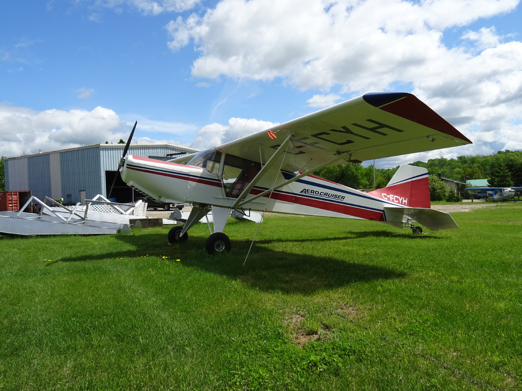
C-FCYH is a 1990 built Normand Dube Aerocruiser of Focus Sport Aviation.
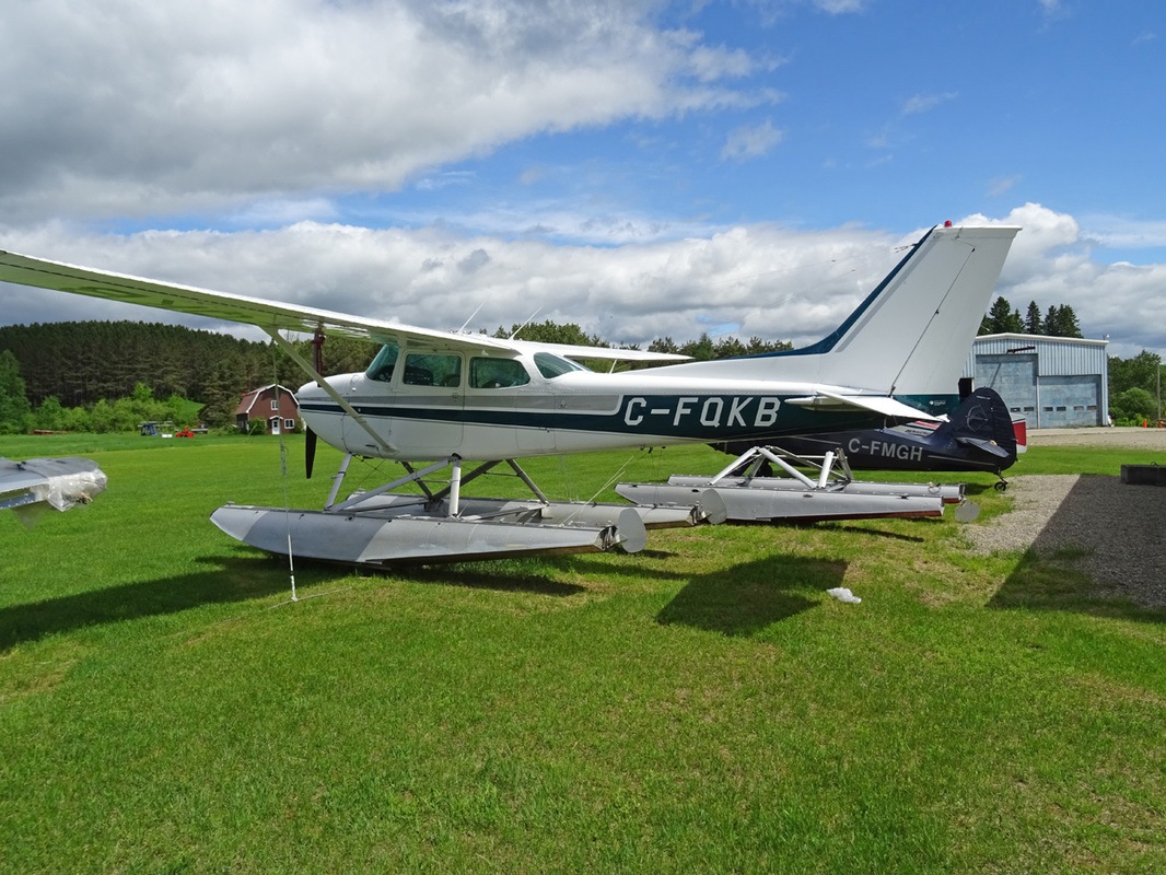
C-FQKB is a Cessna 172L Skyhawk.
The 172L, sold during 1971 and 1972, replaced the main landing gear legs (which were originally flat spring steel) with tapered, tubular steel gear legs. The new gear had a width that was increased by 12 in (30 cm).[15] The new tubular gear was lighter, but required aerodynamic fairings to maintain the same speed and climb performance as experienced with the flat steel design. The "L" also had a plastic fairing between the dorsal fin and vertical fin to introduce a greater family resemblance to the 182's vertical fin.
The 1971 model sold for US$13,425 in the 172 version and US$14,995 in the Skyhawk version. 827 172Ls were sold in 1971 and 984 in 1972.
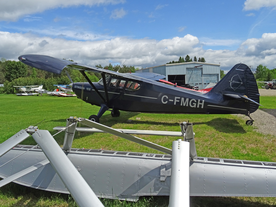
C-FMGH is a 1947 built Stinson 108.
The Stinson 108 was a popular general aviation aircraft produced by the Stinson division of the American airplane company Consolidated Vultee, from immediately after World War II to 1950. It was developed from the prewar Model 10A Voyager.
Stinson was bought by Piper Aircraft in 1949. All Stinson model 108, 108-1, 108-2, 108-3 and 108-4 aircraft were built by Stinson at Wayne, Michigan. When Stinson sold the type certificate to Piper in 1949, approximately 325 airplanes of the 5,260 model 108s built by Stinson were complete but unsold. These 325 model 108s went to Piper as part of the sale. Piper then sold that inventory as the Piper-Stinson over the next few years.
The fuselage was of fabric-covered steel tube. Aftermarket modifiers have obtained supplemental type certificates (STC) allowing conversion to an aluminum covering. Many different engines have been installed in the 108 by STC such as the Lycoming O-360, Franklin 220|220, Continental O-470.
One distinctive feature was the partial leading edge slot installed on the wings and aligned with the ailerons on the trailing edge, ensuring that the portion of the wing containing the aileron remains unstalled at higher angles of attack, thus contributing to docile stall behavior.
Total new production of the Stinson Model 108, by Stinson, was 5,260, total does not include the 2 converted prototypes. Stinson delivered approximately 4,935 aircraft and Piper delivered approximately 325 aircraft. Piper later sold the type certificate to Univair Aircraft Corporation. Univair built and certified the model 108-5, 1 built. Total new model production by Stinson and Univair is 5,261 aircraft.
|
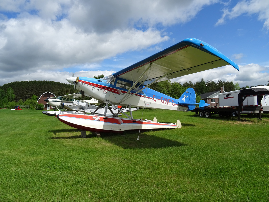
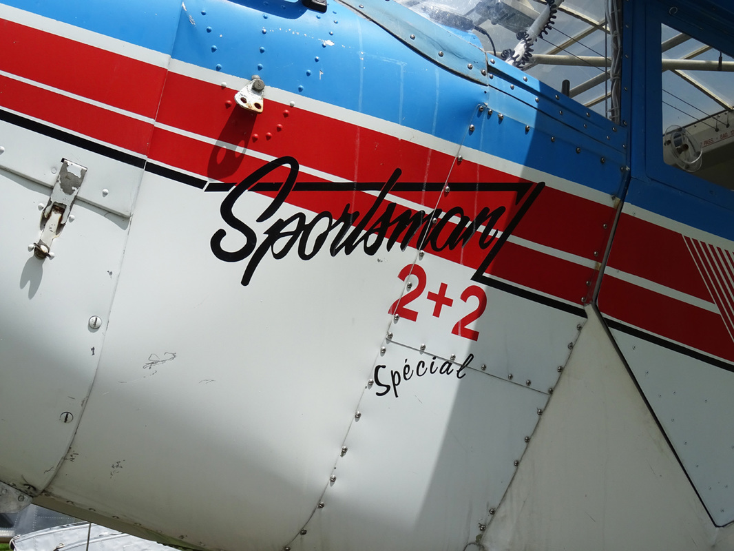
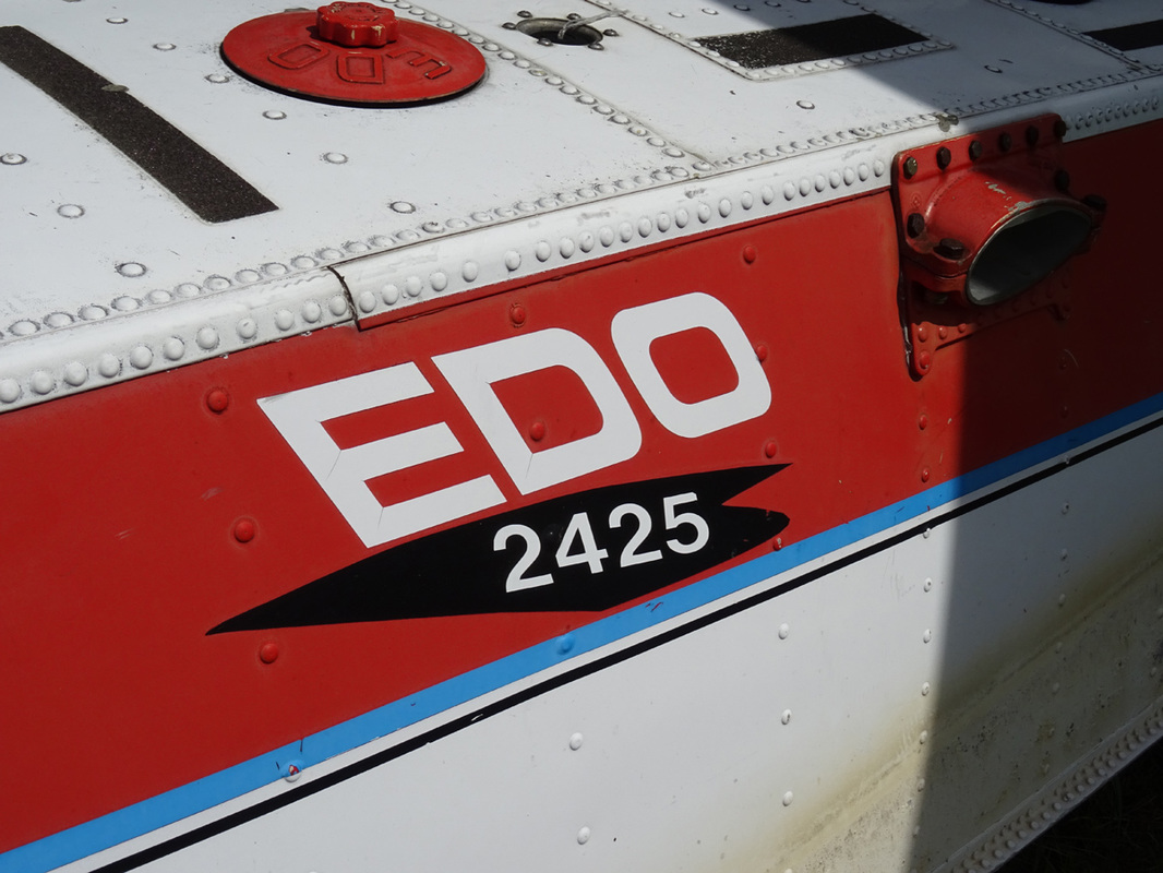
C-GMFO is a Sportsman 2+2 Special and she sits on top colorful Edo 2425 floats.
The Sportsman 2+2 is a reproduction of the Famous PA-14 Family Cruiser. The Sportsman 2+2 is a great family cruiser with its roominess, extra baggage area and increased fuel capacity. The Sportsman 2+2 maintains the docile maneuverability and short field capabilities of our Sport Trainer. The versatility of this airplane makes it ideal as a trainer because of its wide stance landing gear and slow speed characteristics. This aircraft also offers superior float plane performance and is easily accessible with its unique doors and optional turtle deck entry. The Sportsman 2+2 utilizes large tires for off-airport operation and has an instrument panel layout to accommodate full IFR equipment. There is no question that the Sportsman 2+2 is an excellent choice for the sport recreational pilot! The Edo Aircraft Corporation The Edo Aircraft Corporation began operations on October 16, 1925. Although EDO's founder, Earl Dodge Osborn, had dreamed of building airplanes, his first successful product line was EDO floats. Because of a new innovative design, the use of aluminum rather than wood and the simple fact that good runways were hard to find in the 1920s, demand built quickly for the floats. With the outbreak of World War II, the company's focus shifted and EDO began to provide subassemblies for military aircraft. This shift in emphasis led to the company being renamed the EDO Corporation in November 1947. |
|
These all-aluminum floats are rugged, extremely long-lasting, relatively inexpensive, and very easy to repair. I have not yet seen a material which can match aluminum in all these areas, particularly the punishment of rough-water take-offs and landings, and extremes of temperature.
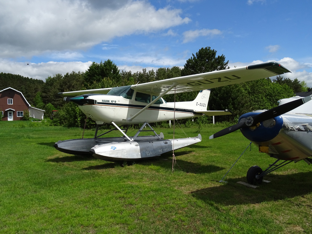
C-GUZU is a Cessna 172 Hawk XP II sitting on top of Edo floats.
The Skyhawk XP (marketingese for Xtra-Performance) introduces higher horsepower and the constant speed propeller to the American 172 market. The XP 195 hp Continental 10-360-K fuel injected engine is actually the well-known 210 hp Continental, but all the muffling required to meet FAA/EPA standards sucked up 15 horses.
The aircraft was well accepted for use on floats, however, as the standard 172 is not a strong floatplane, even with only two people on board, while the XP's extra power improves water takeoff performance dramatically.
|
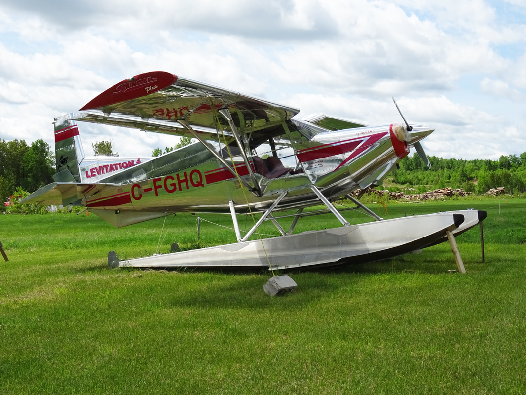
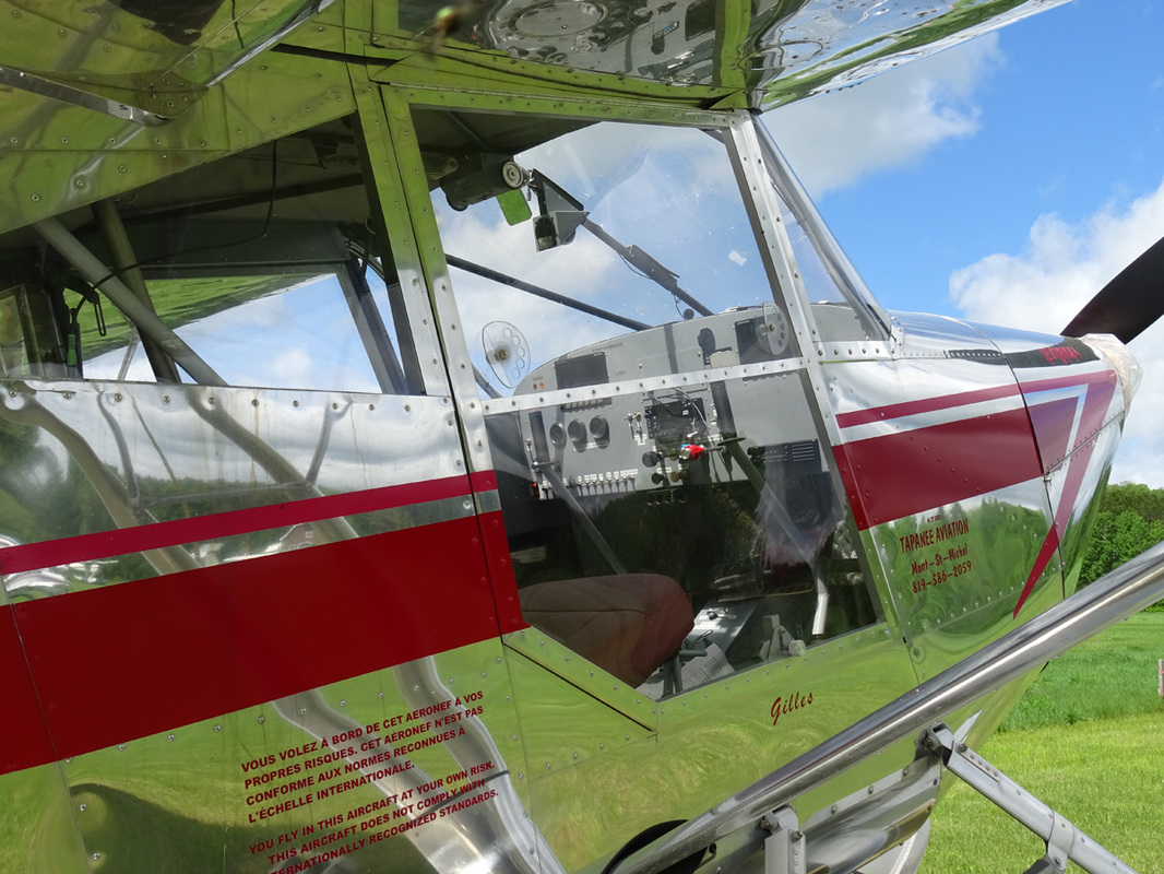
The Tapanee Levitation 4 is a Canadian four-seat STOL aircraft designed to be homebuilt by Michel Lequin for Tapanee Aviation of Mont-Saint-Michel, Quebec.
A larger version of the companies earlier Pegazair bushplane, the Levitation is a high-wing monoplane with V-strut bracing. Powered by a 180 hp (134 kW) Lycoming O-360 flat-six piston engine with a two-blade propeller. The Leviation has a fixed conventional landing gear with a tailwheel and a cabin holding a pilot and three passengers in two rows of side-by-side seating. |
"Next halting place was the small airfield of Mont-Laurier".
Mont Laurier airfield
This 1960s vintage Cessna is parked out at the edge of the airfield where the grass is a bit longer.
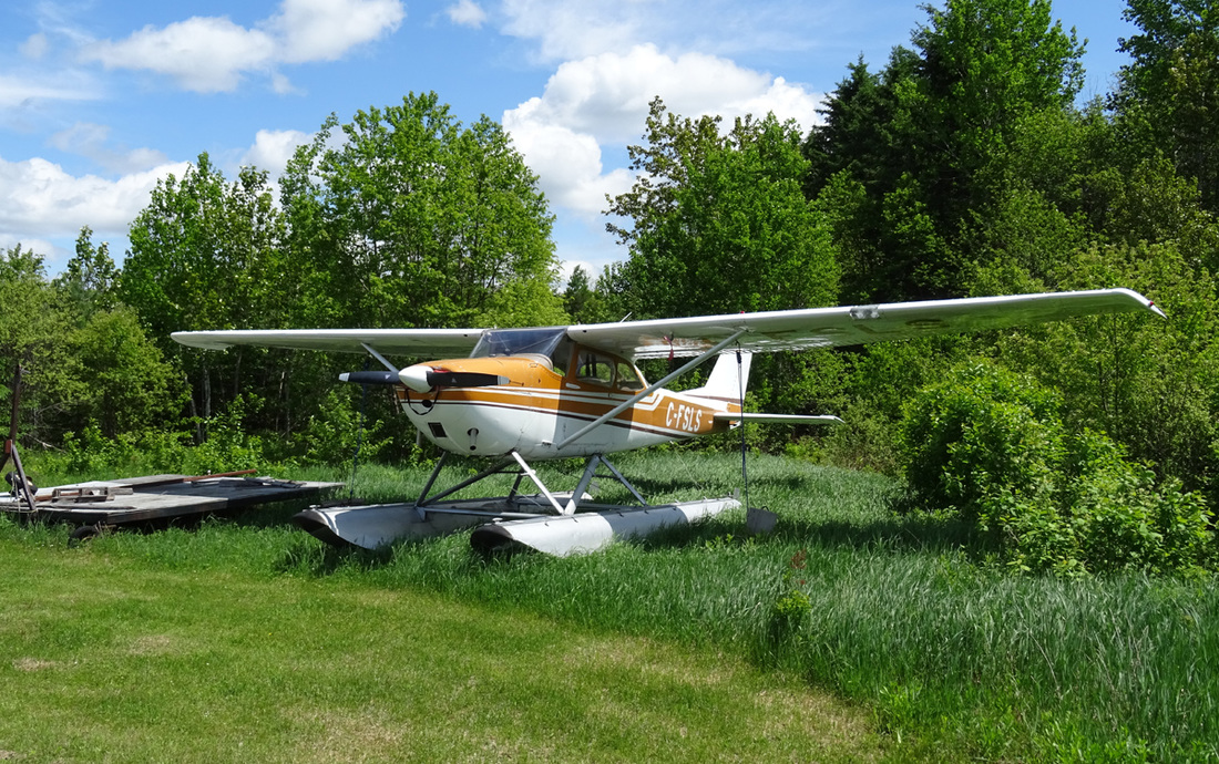
C-FSLS is 1965 Cessna 172F. The 1965 model 172F introduced electrically operated flaps to replace the previous lever-operated system. It was built in France by Reims Cessna as the F172 until 1971.
These models formed the basis for the U.S. Air Force's T-41A Mescalero primary trainer, which was used during the 1960s and early 1970s as initial flight screening aircraft in USAF Undergraduate Pilot Training (UPT). A total of 1,436 172Fs were completed.
These models formed the basis for the U.S. Air Force's T-41A Mescalero primary trainer, which was used during the 1960s and early 1970s as initial flight screening aircraft in USAF Undergraduate Pilot Training (UPT). A total of 1,436 172Fs were completed.
|
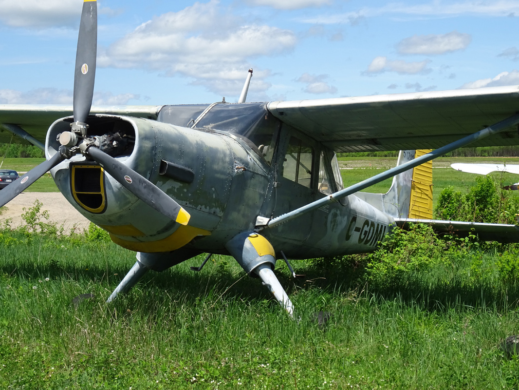
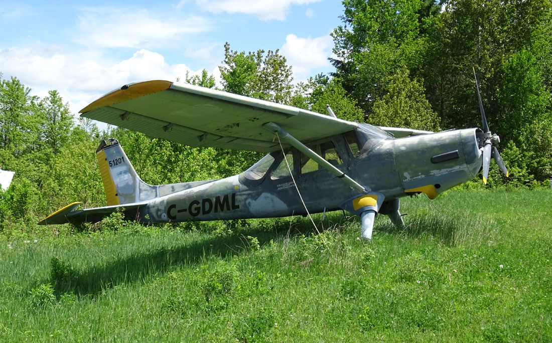
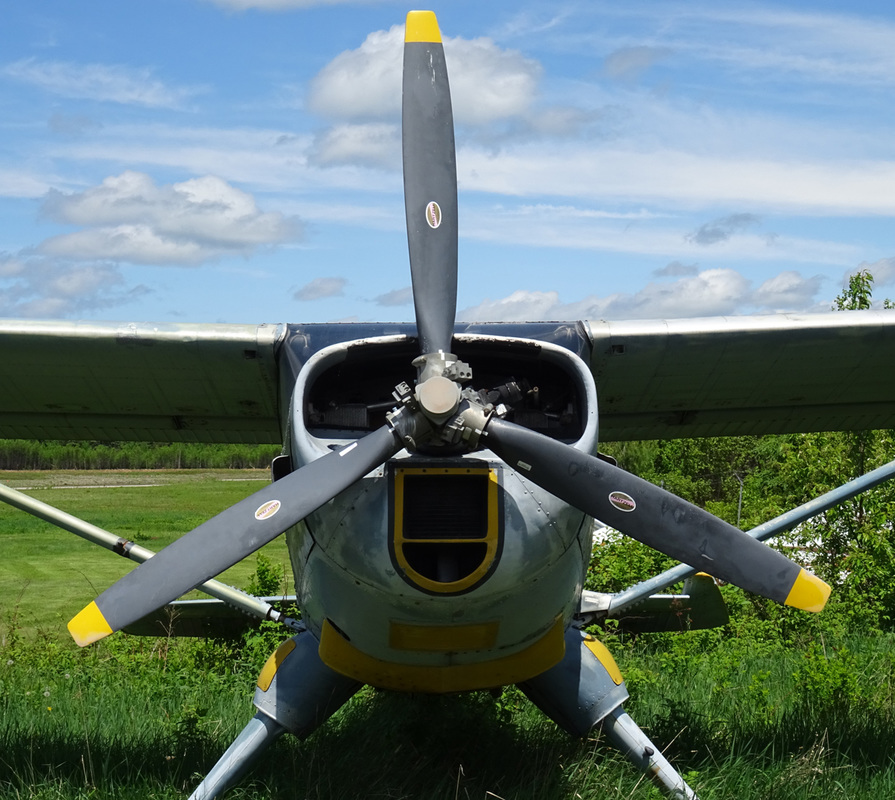
C-GDML, seen here at Mont Laurier airport, is a 1975 built UTVA-66 STOL. 51201 is the plane's production serial number.
Dipl.-Ing. Branislav Nikolic and Dipl.-Ing. Dragoslav Petkovic working for the Fabrika Aviana UTVA at Pancevo, Yugoslavia designed an aircraft intended for the agricultural role, but with many secondary roles. The Utva 56, flew for the first time on April 22, 1959 powered by a 260hp Lycoming GO-435-C2B2. For series-production the sole prototype was developed into the Utva 60, mainly differing in having a 270hp Lycoming GO-480 engine. During development the multi-purpose utility role became the prime target. Small cargo or two stretchers could be loaded through the upward-hinged rear cabin window. The floatplane prototype flew 29 October 1961 equipped with Edo floats, production types were fitted with BIN-1600 floats designed by Nikolic. Early 1967 a refined version of the Utva–60 appeared, having a Lycoming GSO-480 engine. The Utva 66 had among other changes: fixed leading-edge slots, larger tail surfaces, increased fuel capacity and like its predecessor it could be fitted with floats. The aircraft was used by civil and military operators in many roles, like training, medivac, searche and rescue, glider-towing, aerial photography, and agricultural. Over 130 of the Utva 66 were build, including 117 for the Yugoslav Air Force. After service with the Yugoslav AF a large number came on the civil registry, between 1999 and 2001 at least 20 came on the registries of Canada an the USA. |
|
"It was a short drive to Maniwaki from Mont Laurier".
Maniwaki
Maniwaki or Kitigan Zibi, as the local Anishnabeg call it, was once a famous Laurentian Air Services water-base in the mid 50s.
Service aérien gouvernemental operated aerial firefighting aircraft against forest fires in the province. It current had a fleet of 8 Bombardier 415 water bombers. Ship 244 and 245 were based at Maniwaki during my visit in June 2016.
The Canadair 415 is the latest in Canadair's line of multi-role amphibious aircraft beginning with the CL-215 in the 1960s. The Canadair 415 amphibian is a high-wing, turboprop aircraft that evolved from over 25 years of experience with the CL-215 firefighting amphibious aircraft. It features a four-compartment, four-door water tank system that can hold 6137 litres (1621 US gallons) of water/foam mixture and refills its tanks by skimming the surface of any suitable body of water.
The Canadair 415, although externally similar to its predecessor, is quite a new machine. It features Pratt & Whitney Canada turboprops, an air-conditioned glass cockpit, and powered flight controls. Compared to the CL-215, it has increased operating weight and speed yielding improved productivity. Aircraft systems have been updated for easier maintainability.
In its firefighting configuration, the Canadair 415 is ideal for Initial Attack on forest fires; getting to the fire at the earliest stages and repeatedly dropping large amounts of fire suppressing foam.The Canadair 415 amphibian is also well suited to other missions such as maritime surveillance, coastal patrol, search and rescue, utility transport and resource protection
The Canadair 415 production program was launched in October of 1991. The Canadair 415 first flew in December 1993 and the first aircraft was delivered in November 1994.
The Bombardier 415 Superscooper (formerly Canadair CL-415 SuperScooper) is a Canadian amphibious aircraft purpose-built as a water bomber. It is an aircraft designed and built specifically for aerial firefighting and is based on the company's CL-215. It is marketed in the United States as the "Superscooper."
In 1987, following market trends towards more efficient, powerful and reliable turboprop powerplants, Canadair undertook the task of retrofitting 17 CL-215 airframes with the Pratt & Whitney Canada PW123AF engines, providing a 15% power increase over the original piston engines as well as enhanced reliability and safety. The retrofitted aircraft were designated CL-215T and also featured many aerodynamic and systems improvements including powered flight controls, cockpit air conditioning, as well as upgraded electrical and avionics systems. The most notable external features of the CL-215T retrofit were the aerodynamic additions to the wings and empennage.
|
Compared to the CL-215, the 415 has increased operating weight and speed, yielding improved productivity and performance.
The 415 first flew on December 6, 1993, with the first deliveries in November 1994. Orders from several countries soon followed. Derived from its predecessor's nickname, it acquired the name, "Super Scooper" in light of its greatly enhanced performance as a water bomber and fire suppresser. In recognition of its abilities, the aircraft was awarded the prestigious Batefuegos de oro (gold fire extinguisher). The award citation in part read "This is the most efficient tool for the aerial combat of forest fires, key to the organization of firefighting in a large number of countries. The continuous improvements to meet the needs of forest firefighting have made these aircraft the aerial means most in demand over more than 30 years." |
The 415 is currently assembled at the Bombardier Aerospace facility near North Bay/Jack Garland Airport in North Bay, Ontario, where the planes can be seen testing on Lake Nipissing. On June 20, 2016, Viking Air purchased the CL-415 type certificate from Bombardier along the older CL-215 and CL-215T.
Of the 95 built, seven have been removed from service due to accidents.
Based on the success of the CL-215, the company introduced the CL-415, a new-build production series beginning in 1993. The 415 has an updated cockpit, aerodynamics enhancements and changes to the water-release system as well, creating a modern firefighting amphibious flying boat for use in detecting and suppressing forest fires.
|
An air-conditioned glass cockpit and powered flight controls are one improvement over the older CL-215.
The aircraft requires 1,340 metres (4,400 ft) of flyable area to descend from 15 metres (49 ft) altitude, scoop 6,137 litres of water during a 12-second 410 metres (1,350 ft) long run on the water at 70 knots (130 km/h; 81 mph), then climb back to 15 m altitude. The aircraft can also pick up partial loads in smaller areas and can turn while scooping, if necessary. One of two probes under the aircraft. This is what actually scoops the water up into the tanks using only the velocity of the aircraft. These probes usually lie flush with the body, as in the left image, and are extended only when scooping. You can pull them down with your hand to get a better look. The 415 can scoop up to 6,140 litres (1350 Imperial gal or 1,620 US gal) of water from a nearby water source, mix it with a chemical foam if desired, and drop it on a fire without having to return to base to refill its tanks. The 415 was specifically developed to provide the capability to deliver massive quantities of suppressant in quick response to fires. The aircraft is built for reliability and longevity, with use of corrosion-resistant materials. Looking aft from the entry point, you can see the top part of each water tank. The top of the tanks open out through the fuselage to allow excess water taken in while scooping to vent back into the lake. Two of the 4 hydraulic tank doors are visible from either side. Pilots can control how many and how quickly the doors open to adjust the drop pattern. A probe housing is also visible aft of the doors. |
|
|
C-GBYY is a 1984 built Wagaero SUPER-CUBY of Geosphair Aviation Inc.
C-FNKM is a 1955 built Cessna 170B. The Cessna 170 is a light, single-engined, general aviation aircraft produced by the Cessna Aircraft Company between 1948 and 1956. The Cessna 170 is a good, honest taildragger and has had very few AD notes on either the airframe or engine. During the late 1940s through the mid-1950s over 5,000 Cessna 170s were manufactured and well over half that number survive today. This alone should indicate that this aircraft has certain qualities that make it a desirable aircraft to own and has also gained it recognition as a Neo-Classic in various aircraft organizations. |
|
"I put 'the General' into drive and started trying to find the hide away waterdrome of Marina Messines at Lac Blue Sea".
Blue Water
The waterfront scene at Marina Messines at Lac Blue Sea.
A private DHC-2 Beaver sits next to Lac Blue Sea awaiting to be pushed back in her natural element!
|
De Havilland DHC-2 Beaver C-FJKH has construction number 988. This Beaver was built by de Havilland 60 years ago, in 1956 and delivered as CF-JKH to the Advocate Mines Ltd. ‘Kilo-Hotel’ has spent a good part of its lifetime working as a sky-truck for the Canadian mining industry and finally ended up at Blue Lake, Quebec arond 2015. It seem she is registrated to '880914 Alberta Ltd' since October 2000.
History file: Fate struck a blow when it crash-landed Watson Lake, Quebec, on December 27, 1967. Following take-off the shoreline of the lake was crossed as the aircraft reached an altitude of appprox. 200ft. The engine failed and the aircraft was turned to the left to carry out a forced landing on the lake. Due to the low altitude and airspeed, partial control was lost and the aircraft contacted the snow surface heavily. The engine failed because of fuel starvation, caused by a sheared shaft in the fuel pump. |
C-FUTJ is a 1966 built Cessna 172G.
The 1966 model year 172G introduced a more pointed spinner and sold for US$12,450 in its basic 172 version and US$13,300 in the upgraded Skyhawk version. 1,597 were built.
The 1966 model year 172G introduced a more pointed spinner and sold for US$12,450 in its basic 172 version and US$13,300 in the upgraded Skyhawk version. 1,597 were built.
A powerful Beaver with some nice looking scenery to go along with it.
"That late afternoon I drove the freeways eastward to Ottawa, where Canada's Aviation & Space Museum is situated
on the banks of mighty Ottawa River near the famous Rockcliff flying & yacht club".
on the banks of mighty Ottawa River near the famous Rockcliff flying & yacht club".
