DeHavilland DHC-2 Beaver
|
Description of the De Havilland DHC-2 Beaver
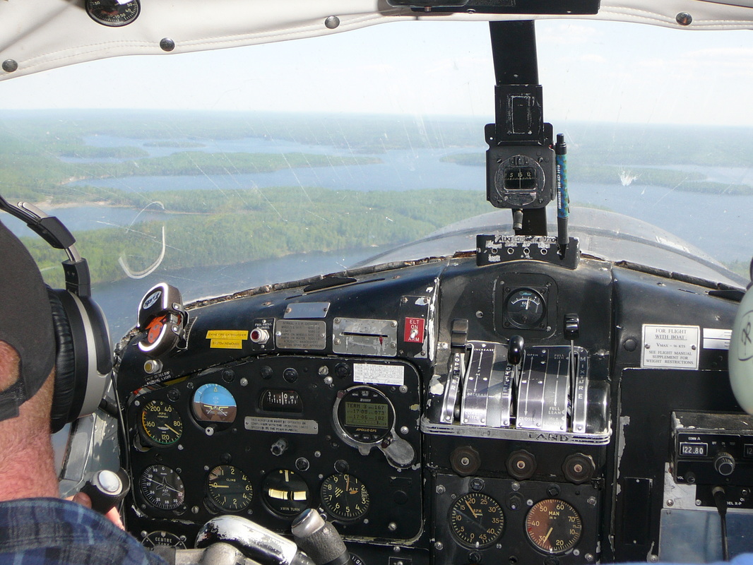
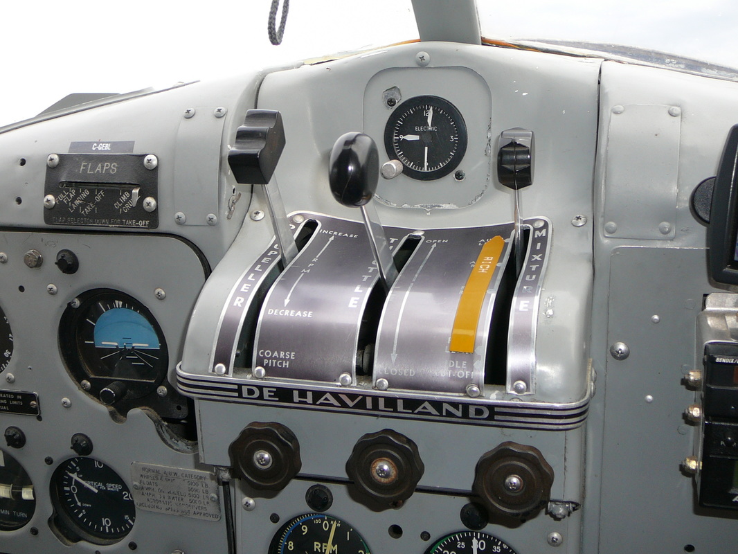
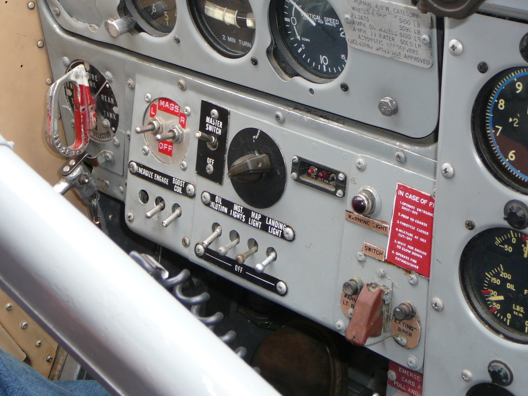
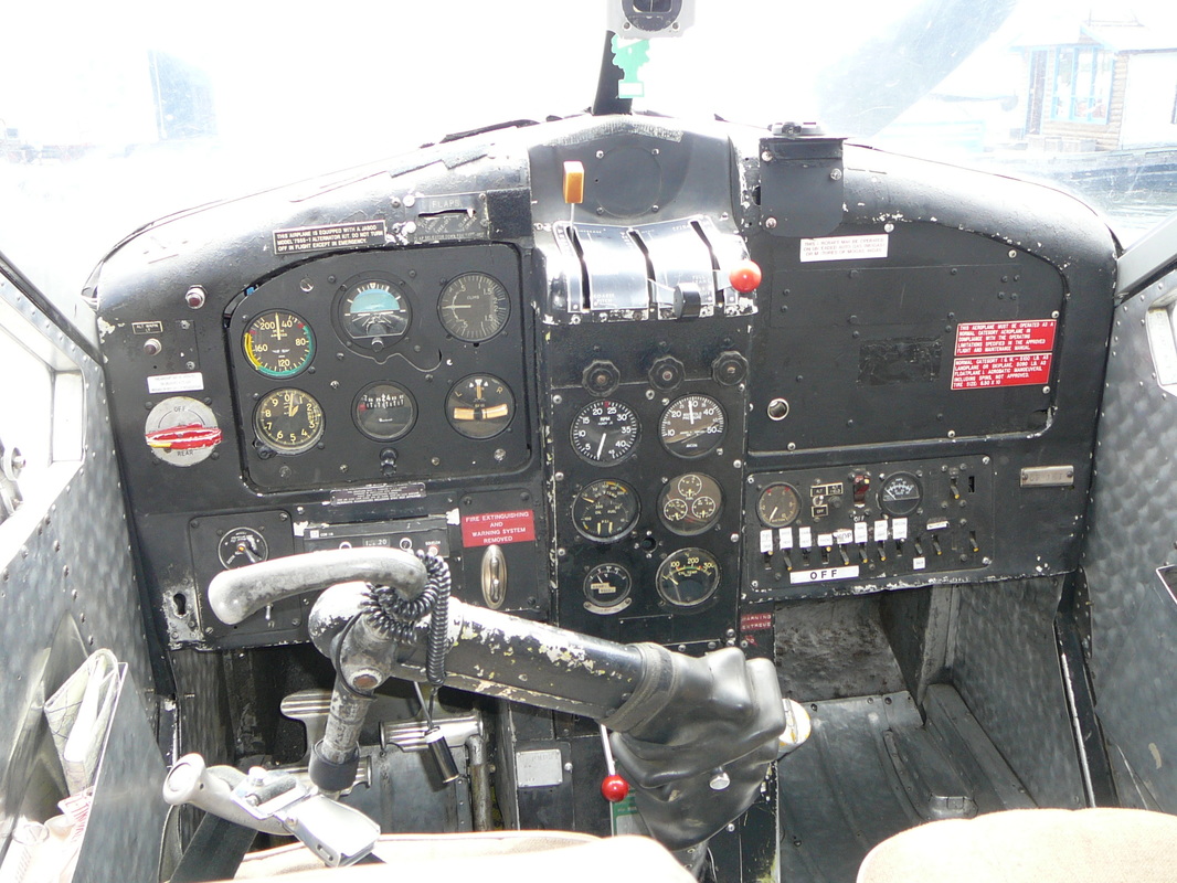
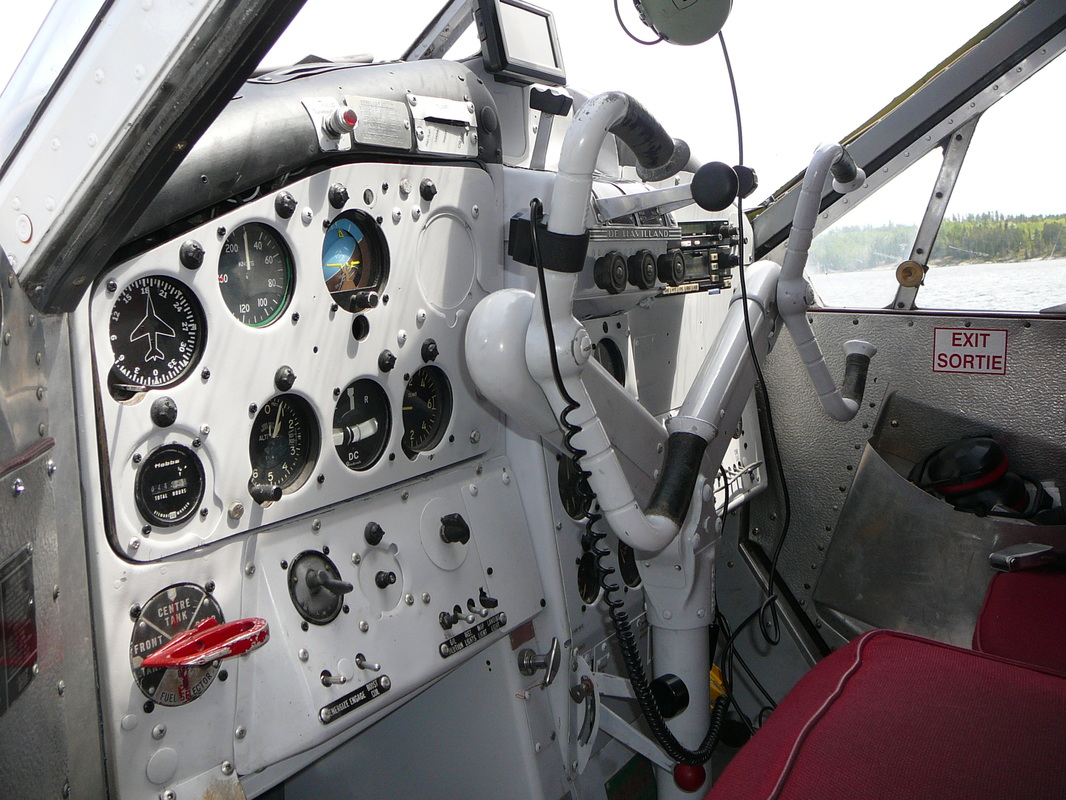
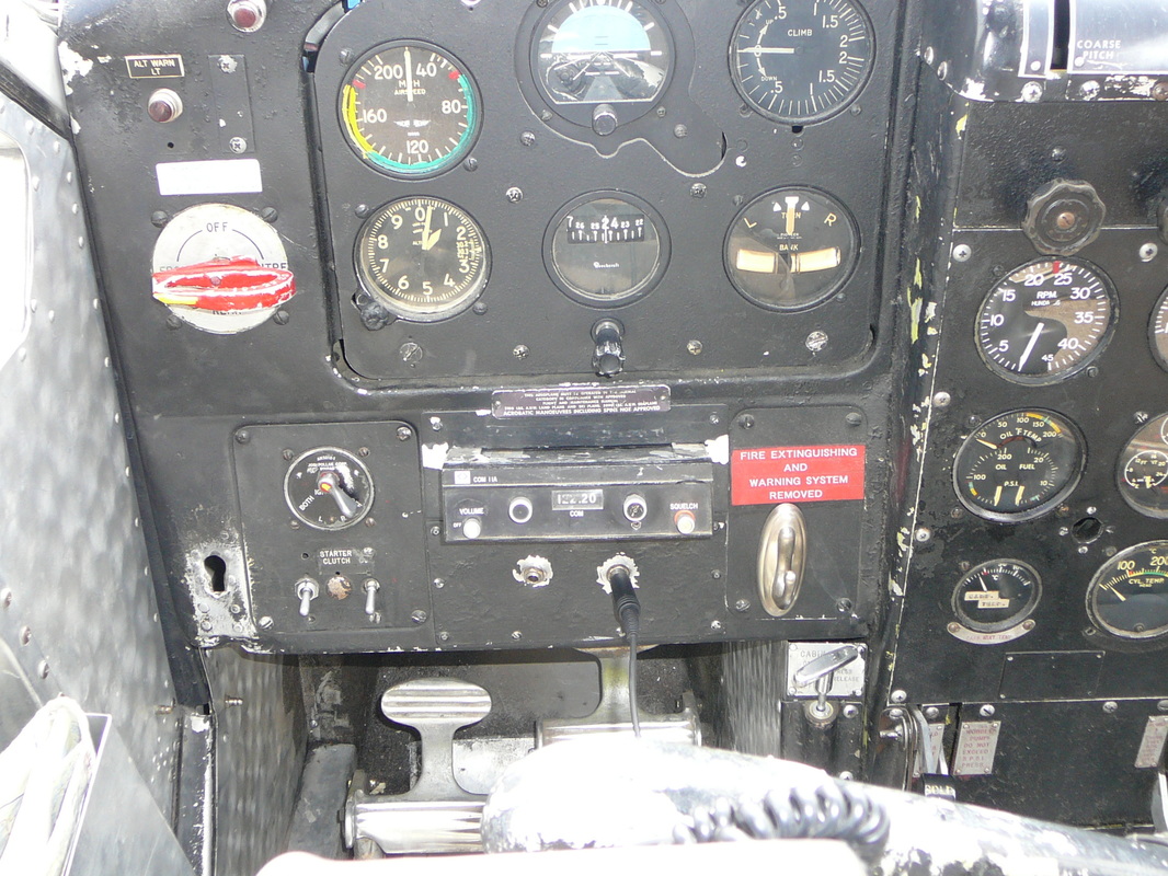
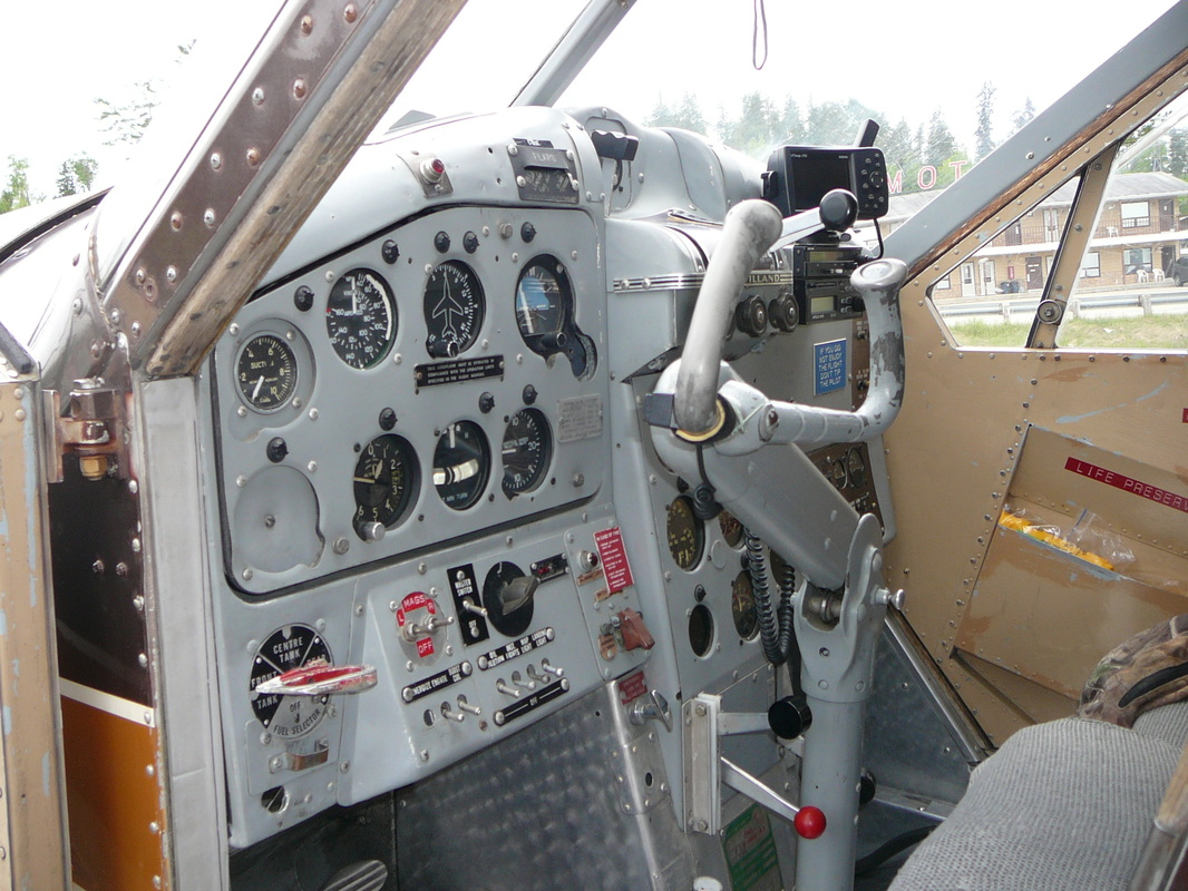
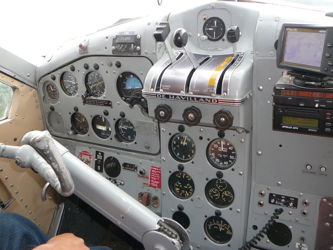
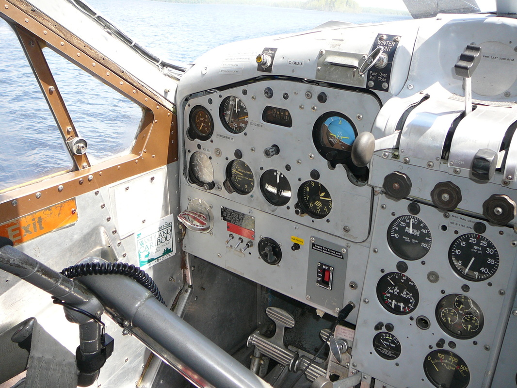
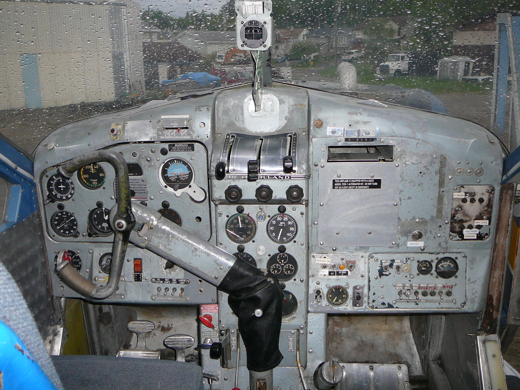
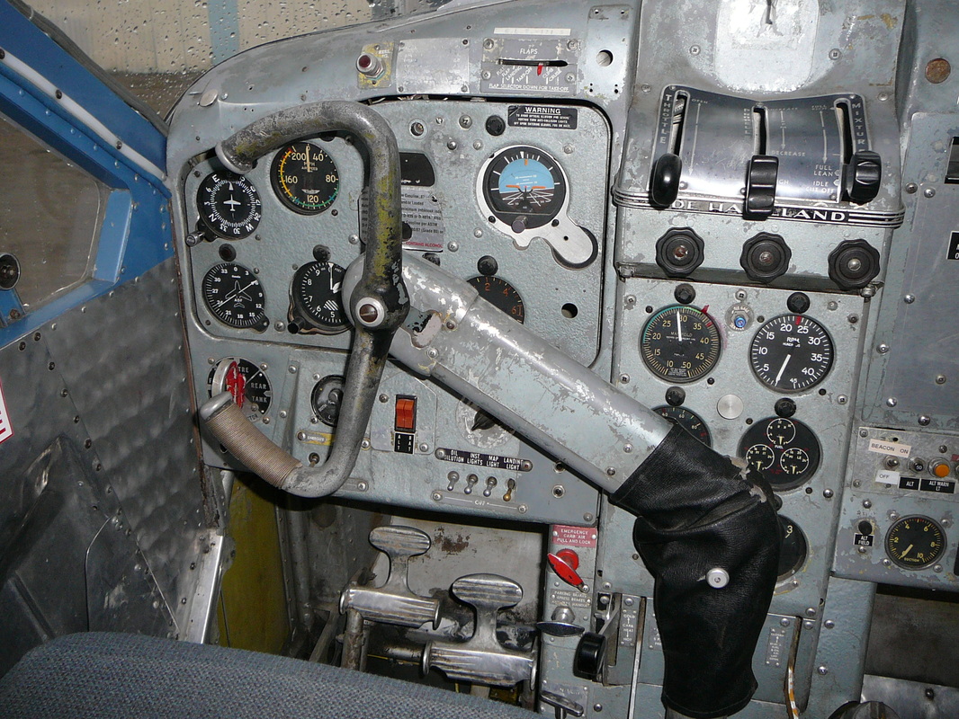
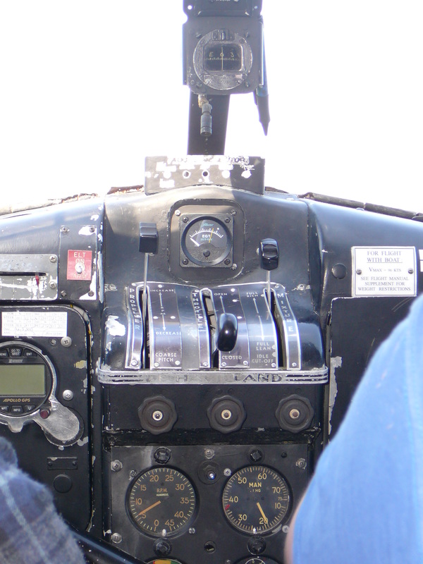
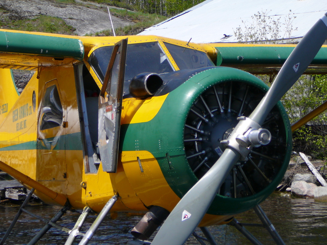
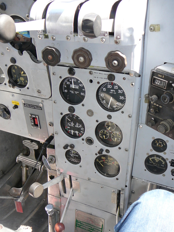
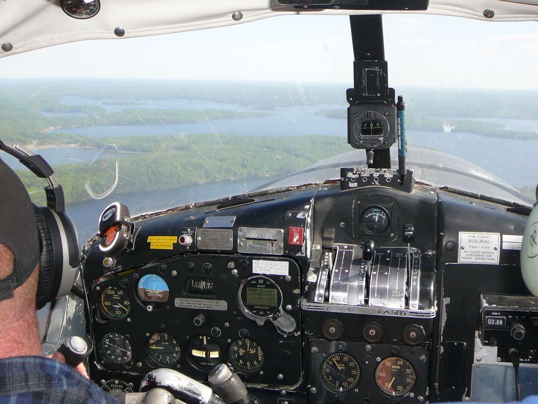
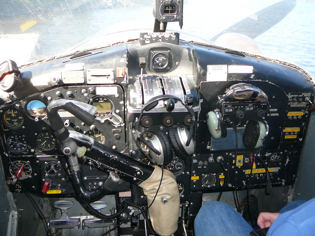
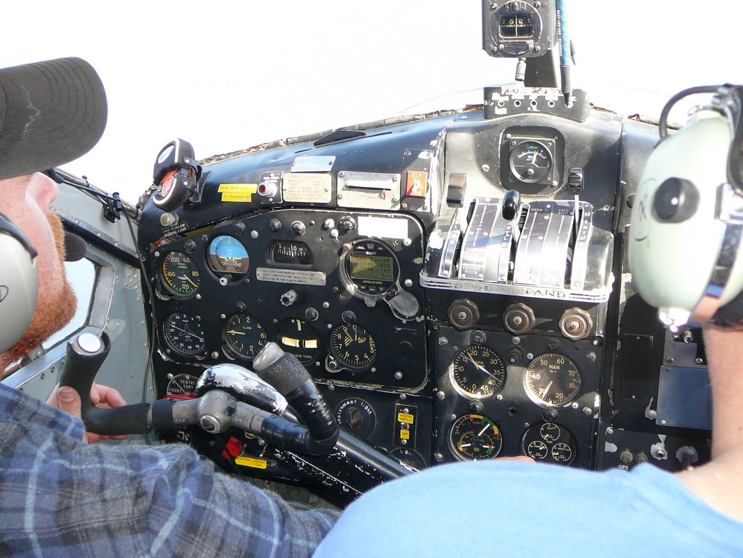
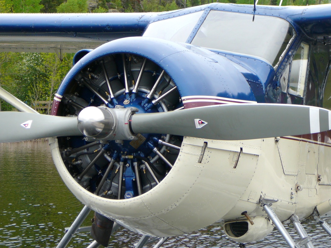
as describe in the Flight Manual of 1957 The DHC-2 Beaver aircraft is an all-metal high-wing monoplane, designed to carry a pilot and seven passengers. The aircraft is powered by a Pratt & Whitney ‘Wasp Junior’ model R-985SB3 nine-cylinder single-row radial engine, rated at 400 BHP at 5,000 ft altitude. The engine drives a Hamilton-Standard constant-speed propeller; crankshaft and propeller rotation being clockwise. Propeller diameter measures 8 ft. 6 in. The supercharger is an engine-driven single-stage centrifugal type. The engine control quadrants are located at the top of the pedestal. Friction control knobs, one below each control lever, increase lever friction when rotated clockwise. The throttle lever movers in a quadrant marked OPEN and CLOSED. The lever is connected to the throttle valve by means of pus-rods and torque-tube linkage. The mixture lever moves in a quadrant marked as follows: AUTO LEAN – AUTO RICH – FULL RICH – FULL LEAN – IDLE CUF-OFF. The lever is connected to the carburetor by means of push-rods and torque-tube linkage. The carburetor heat control lever is located below the engine instrument panel and is cable-connected to a gate valve in the carburetor air intake duct. When the lever is selected up to the COLD position, cold ram air enters the carburetor through the air intake duct. As the lever is moved down towards the HOT position, the gate valve progressively closes the cold air intake while opening the warm air duct. This second duct allows heated air, from inside a heat exchanger muff surrounding a section of the engine exhaust collector, to mix with the cold ram air before delivery to the carburetor. Intermediate position of the lever between fully up and fully down will therefore give varying degrees of carburetor air intake temperature. With the lever in the HOT position the ram air intake is fully closed and heated air only is ducted to the carburetor. For operation in desert areas a dust filter for the ram air intake can be installed. A carburetor mixture temperature gauge in the engine instrument panel indicates the resulting mixture temperatures. The lower air induction system consists of an air scoop in the lower engine cowling (later the air scoop could be replaced on-top of the cowling) feeding unfiltered air through a duct and into the carburetor. This system can be equipped with a hinged, dry air filter mechanically connected to a carburetor air filter control installed above and to the right of the engine controls quadrant. The control is marked CARB AIR, IN-RAM, OUT-FILTER and arrowed counterclockwise with TURN TO UNLOCK. At the RAM position the filter lies flush with the bottom of the air scoop and allows unfiltered ram air to enter the carburetor. At the FILTER position, the forward end of the filter is raised so that air entering the scoop must pass through the filter before entering the carburetor. The control must be turned clockwise to lock in either position. Under no circumstance must the CARB AIR control remain in any intermediate position between IN-RAM and OUT-FILTER. In and intermediate position the filter will cause a blockage in the induction system. The effect of the filter is to reduce the 5,000 foot critical altitude by approximately 800 feet. Below this new critical altitude there is no loss in engine power, while above this altitude the power loss is small. The engine may be started with the CARB AIR control in the RAM position to avoid damage in the filter in case of back-fires. Immediately after starting the engine, in areas wherever there is a possibility of dust, sand or dirt entering the intake, the control should be moved to and remain at FILTER position for all ground running, taxiing and take-off and during flight if necessary. Take-off from a short field, at or above the new critical altitude, should be made with the CARB AIR control at RAM position, Before landing in dusty or sandy areas, the control must be selected to FILTER and remain in this position while the aircraft is on the ground, except when starting the engine as previously explained. The upper air induction system consists of an air scoop on the top right of the engine rear cowling feeding air through a duct, at the right side of the engine, and through a filter to the carburetor. In this installation the induction air is filtered at all times and there is not pilot control, except during emergency operation when the filter is by-passed. An emergency air handle, marked EMERGENCY CARB AIR-PULL & LOCK, is provided at the left of the engine controls pedestal. Operation of the handle mechanically opens a flap valve in the duct directly below and leading into, the carburetor. The flap valve is opened by turning the handle counterclockwise, thus breaking the lock wire. The handle is then pulled fully out and turned clockwise to lock the flap valve fully open. In this position an emergency air inlet to the carburetor is provided, in the event of a blockage in the main induction system. To maintain the carburetor mixture temperature within the limits, heated air can be admitted at the left side of the air scoop duct by selection of the carburetor heat control lever. The air is heated by passing through a heater muff surrounding part of the exhaust manifold. A rotary four position ignition switch, located on the STARTER PANEL below the flight instrument panel, is marked OFF, L, R and BOTH. A boost coil switch, located on the starter panel, is spring-loaded to the OFF position. When the switch is held to the BOOST COIL position, high tension electrical current is supplied to the engine spark plugs to initiate starting. The hand-operated cylinder primer pump is on the floor to the left of the pilot’s seat. The pump handle is pushed down and rotated anti-clockwise to unlock and after use, relocked by pushing it down and rotating it clockwise. The engine is started either by an electrical direct cranking starter motor. The starter switch for the electrical direct cranking starter motor and the starter clutch and boost coil switches require for the electrical inertia starter are located on the starter panel below the flight instrument panel. Conventional engine instruments are mounted on a panel below the engine controls quadrant on the pedestal. The engine instruments consist of: Tachometer, Manifold Pressure Gauge, Cylinder Head Temperature Gauge, Carburetor Mixture Temperature Gauge, combined Oil and Fuel Pressure and Oil Temperature Gauge. The starter Brush Release Socket is also located on the engine instrument panel. The engine drives a Hamilton-Standard two-bladed 8 ft. 6 inches diameter constant speed, counterweight type propeller having a pitch range for 11.5 to 24 degrees. |
|
|
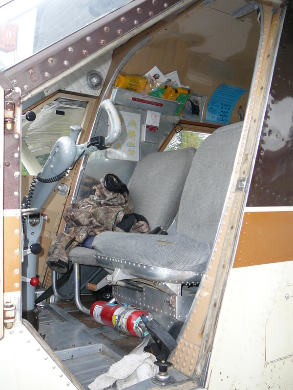
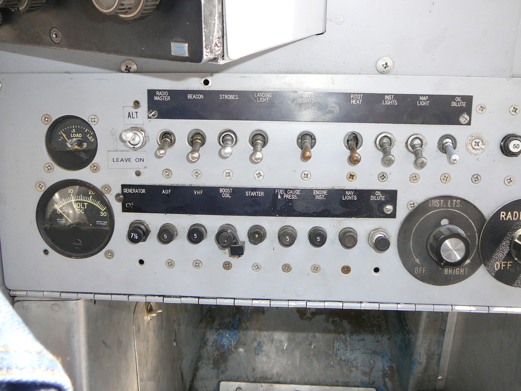
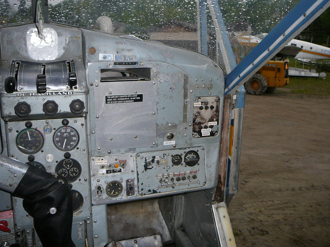
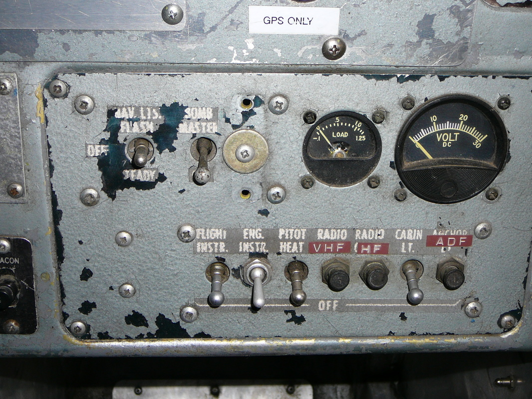
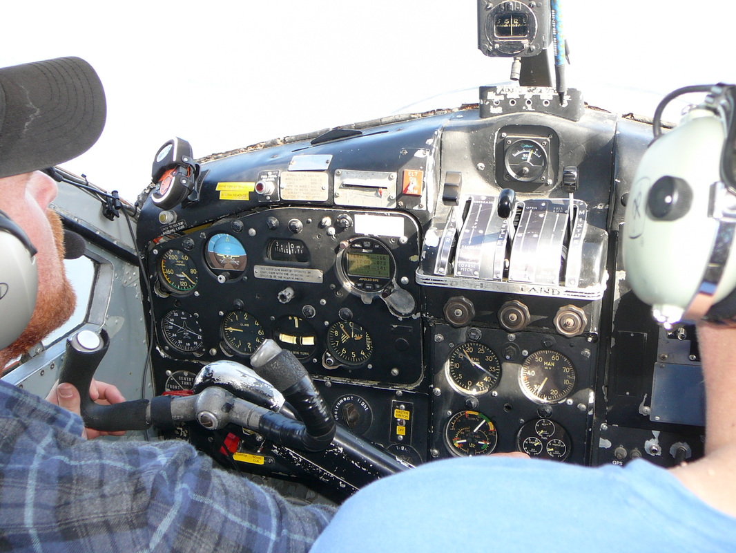
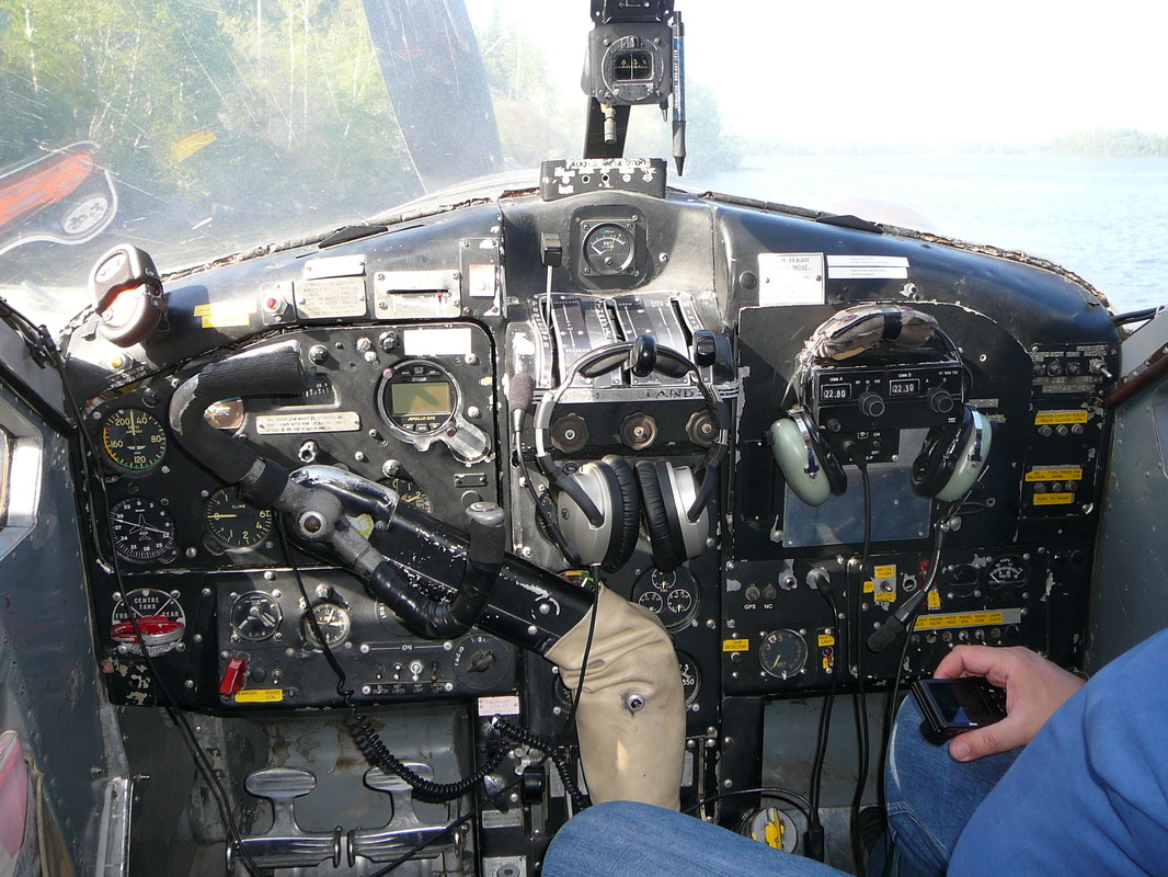
The propeller lever in the engine controls quadrant on the top of the pedestal and sled in a gate marked RPM, DECREASE and INCREASE. It is connected by a push/pull rod linkage to the propeller governor. The governor retains the selected rpm constantly, within the operating range of the propeller, regardless of variations in air loads of flight attitudes. When INCREASE RPM is selected the governor directs oil from its own engine driven pump to the propeller, at pressure, which hydraulically moves the propeller blade, in opposition to the counterweight, to lower angels. When DECREASE RPM is selected the governor allows oil from the propeller to return to the engine sump and the counterweights mover the blade to higher angles. The oil tank is located aft of the fire-wall and is serviced from inside the cockpit through a filler at the base of the pedestal. The capacity is 5 ¼ imperial gallons. Fuel is contained in three tanks under the cabin floor which are used separately. They are serviced through three filler necks in a filler compartment protected by a hinged door on the forward left-hand side of the fuselage, adjacent to the cockpit door. For long range operation non-jettisonable wing tip tanks may be installed to replace conventional wing tips. Fuel from these tanks is gravity fed to the front tank. The fuel transfer selector, for use when wing tip tanks are installed, is located to the left of the pilot, above the cockpit door window. It has four positions marked LH, RH, BOTH and OFF. A fuel wobble pump lever, below the engine instrument panel on the pedestal, is used to build up the fuel pressure to 5 psi, for starting the engine. The emergency shut-off lever, on the right side of the pedestal, below the engine instrument panel, is normally wirelocked in the down position. When pulled sharply up to break the wire lock and moved to the closed position, it cuts off the supply of both fuel and oil to the engine. A triple indicator fuel contents gauge, located on the right side of the engine instrument panel, is graduated in Imperial gallons, in white and red figures for in-flight and tail down positions respectively. A combined fuel pressure, oil pressure and oil temperature gauge is located on the left side of the engine instrument panel. On some aircraft a red warning light, which lights up when the fuel pressure drops to 3 psi, is positioned above the flight instrument panel. Description of the De Havilland DHC-2 Beaver as describe in the Flight Manual of 1957 , continued … Electrical DC energy is supplied by a 50 amp 28-30 volt generator in conjunction with a 24 volt 17 amp/hr. battery. The generator output is regulated by a carbon pile voltage regulator. A reverse-current relay is used to protect the generator when is not charging. The battery is stowed in a compartment on the left side of the fuselage, aft of the cabin door and is accessible through a hinged panel on the outside of the aircraft. Nowadays, many Beavers have battery forward modification which has a positive outcome on the CG of the aircraft. The following equipment and controls are operated by the electrical system: Starter, Oil dilution system, Booster pump (if installed), Engine indicators, Fuel contents gauge, Interior lights, Navigation lights, Landing light, Anchor lights (seaplane), Fuel pressure warning light, Electronic equipment, Pitot head heater and Fire warning system. The generator field switch, located on the electrical switch panel, is of the single-pole, single throw type. The battery master switch is located in the left-hand upper corner of the flight instrument mounting panel. It is of the double pole, single-throw type and interrupts the battery output to the electrical system. A volt-ammeter, located in the electrical switch panel, indicates the amperage of the generator supply. The voltage of the generator supply is indicated when charging by pressing the stud at the lower left of the instrument. When the generator is not operating, the battery voltage only will be indicated. The control surfaces are conventionally operated by a control column and rudder pedals. The upper portion of the control column carrying the handwheel, may be ‘thrown-over’ for use by a co-pilot in conjunction with the rudder pedals on the right side of the cockpit. The ailerons are differentially rigged to give a larger upward then downward displacement are drooped when the wing flaps are lowered through the first 15 degrees. Trim tabs, adjustable in flight, are fitted to the elevator and rudder. A lock plunger at the hinge point of the control column locks the hinged upper portion of the column in position. The control column can be thrown over during level cruising flight without disturbing the balance of the aircraft by grasping the upper portion of the column and allowing the handwheel free movement as the upper portion is ‘thrown-over’ for use by the co-pilot. The elevator trim is adjusted by twin handwheels on the cockpit roof, operating in the natural sense. A pointer and scale, between the handwheels, marked NOSE UP, NOSE DOWN, indicate the direction and degree of trim applied. The rudder trim is adjusted by a handwheel on the cockpit roof, just aft of the elevator trim handwheels. A pointer and a scale marked LEFT and RIGHT indicate the direction and degree of the trim applied. The wing flaps are of the slotted type and extend from the wing roots to the inboard ends of the ailerons which also droop in conjunction with the flap movements. The flaps are operated by an actuating cylinder located in the fuselage at the left-hand wing root. Hydraulic fluid is supplied to the actuating cylinder by a handpump, under the pilot’s seat. This handpump has an integral reservoir, a selector valve and a relief valve. The relief valve is set at 1,000 psi. The wing flap hand pump lever is at the right-hand side of the pilot’s seat and is operated in a fore-and-aft direction. The wing flaps selector lever is located on the right-hand side of the pilot’s seat. It has two marked positions, UP and DOWN. Intermediate positions of the wing flaps are selected by moving the selector lever to UP or DOWN then pumping the wing flaps with the hand pump lever to the desired position, as shown on the wing flaps indicator. If the flaps are in any lowered position, it is essential that the selector lever is retained in the DOWN position. When the flaps are retracted, the selector lever must be retained in the UP position. Once the selector lever is set to DOWN and the flaps are pumped to the desired position, the selector lever must not be moved until it is desired to change the flap position. A wing flaps position indicator is situated above the flight instrument panel. It is marked FULL FLAP, LANDING, TAKE-OFF, CLIMB and CRUISE. FULL FLAP is only required for emergency landing in very restricted areas. In many float equipped Beavers one still can find the parking brake. Its located on the left side of the pedestal, just above the wobble pump handle. A shock-mounted flight instrument panel is provided for the pilot and incorporates and altimeter, turn-and-bank indicator, rate-of-climb indicator, air speed indicator, directional gyro and artificial horizon. The airspeed indicator, altimeter and the rate-of-climb indicator, are operated by the pitot static system, The static opening is incorporated in the left-hand side of the rear fuselage. The directional gyro, artificial horizon and turn-and-bank indicator, are operated by the vacuum system. A vacuum gauge on the right of the electrical switch panel indicates the vacuum in In.Hg. being applied to the instruments. The outside air temperature gauge is located in the cockpit roof. It is of the direct-reading bulb type and the dial is graduated in both Fahrenheit and Centigrade scales. The artificial horizon is powered by the vacuum system. Its horizon bar gives a dive, climb and angle of bank indication. A knob at the bottom of the instrument dial permits adjustment of the instrument to any fore-and-aft attitude of the airplane within limits of plus or minus 7 degrees Celsius. A caging knob on the instrument erects the gyro and locks the horizon bar in the horizontal position. This knob must be in the uncaged position before take-off to insure proper indications from the instrument. The operating limits are set to permit 70 degrees climbs and glides and 100 degrees right or left banks before the limit stops are reached. If exceeded, the caging knob provides a rapid means for resetting the artificial horizon. The magnetic compass is mounted on a bracket attached to the windshield center post. The switch for the compass light is on the electric switch panel. A compass deviation card is mounted above the compass. A hand operated fire extinguisher is stowed in a quick release clip on the floor, in front of the pilot’s seat. The engine fire extinguisher system is controlled form the fire extinguisher panel below the flight instrument panel. The system incorporates a fire extinguisher bottle, a flame switch and a length of fuse wire located in the engine accessories compartment. In the event of fire, the red fire warning light on the extinguisher panel is illuminated. The engine should then be switched off before switching the EXTINGUISHER SWITCH-ON to discharge the contents of the bottle inside the engine cowling. Both the warning light and the extinguisher circuits are protected by push-to-reset button type circuit breakers on the fire extinguisher panel. A first aid kit is located on the back of the pilot’s seat. The pilot’s seat is simultaneously adjustable fore-and-aft and for height by means of a screw jack on the front of the seat; a lap type safety belt is provided. The seat cushion has grab-lines and may be used as a life-preserver when abandoning the aircraft in or over water. Hot air for heating the interior of the cabin is supplied by ram air passing through a heat exchanger tube in the engine exhaust system. From a four-way outlet at the center of the cockpit floor, the heated air is ducted to the pilot’s seat and front passengers feet and to two outlet grills in the cabin floor. A heated air outlet at the top of the instrument panel permits defrosting of the pilot’s windshield. All hot air outlets are controlled simultaneously by a push-pull control, on the base of the pedestal which permits intermediate positions between ON in its up position and fully OFF. Two ventilation louvers, one on each side of the cockpit roof, to the left and right of the pilot and co-pilot, supply ram air to the cabin from screened openings in the leading edge of each wing root. The ventilation louvers are adjustable. They open when the knob, on the side of the louver, is turned clockwise. Intermediate positions between OPEN and SHUT are possible. To control the direction of airflow from the louver, its body can be moved to point in any required direction. An exhaust type circular grill and shutter ventilator in the cabin roof exhausts air from the cabin. Necessary suction is provided by a rearward facing air scoop on top of the fuselage. For operation in extreme cold conditions, engine winter shuttersmay be installed. The shutter assembly consists of a fixed out shutter. The winter shutters control handle is located to the left of the engine controls. When the handle is in, the shutters are OPEN; when fully out the shutters are SHUT. The handle, when rotated clockwise, engage a pawl which locks the shutters in the OPEN, SHUT or any intermediate position. |
|
|
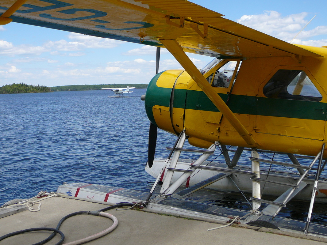
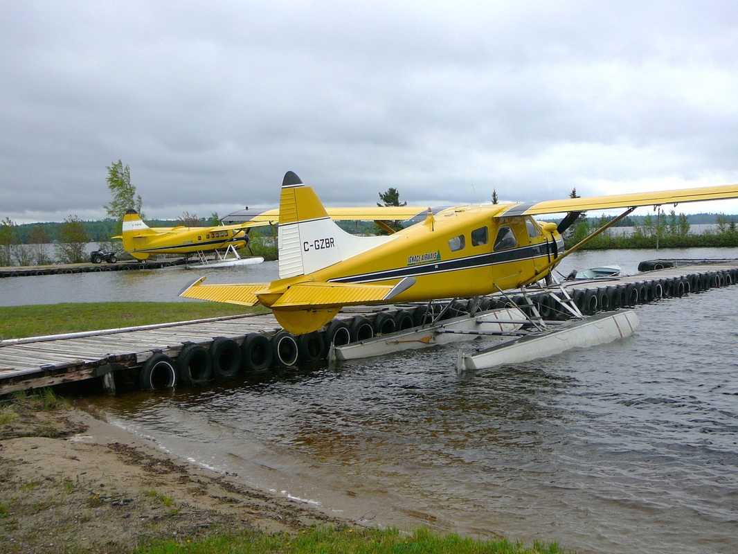
Repair and overhaul companies Besides Kuby’s other repair and overhaul companies are Kenmore Air of Union Lake, Washington, USA and Sealand Aviation of Vancouver Island. Sealand was founded in 1981 and is based in Campbell River, BC, Canada. All these companies have the following modifications available for the DHC-2 Beaver: Three-Blade Propeller Due to its shorter diameter, the three-blade propeller is smoother, quieter and less subject to blade damage than a two-blade propeller. There's also a weight saving of 56-61 pounds and a cost saving of up to 50 percent at overhaul time. Battery Relocation Replacing the original battery with a smaller one and relocating it from aft of the cabin to the firewall offers four advantages: 1/. Empty weight is reduced by up to 72 pounds 2/. Center of gravity is moved forward 3/. Battery can be warmed along with the engine during winter pre-heating 4/. Extra space is available for baggage Alternator System In this modification, the original, heavy generator is replaced with a lightweight 50-amp alternator that features solid-state control units. The kit lowers the aircraft empty weight by up to 33 pounds and provides battery charging at a lower RPM. Enlarged Rear Windows Large, rectangular rear windows replace the original porthole windows, greatly improving visibility for both passengers and the pilot. Bubble Cabin Door Windows Sightseeing zooms with installation of bubble-type windows in the cabin doors because passengers can view surface objects normally invisible through flat windows. Bubble windows also provide extra shoulder room when three passengers sit abreast in the center seat. Seaplane Fins To minimize bumping the dock with a ventral-mounted seaplane fin the smaller fins mounted higher on each outboard end of the horizontal stabilizer were developed. Next to this the smaller overall surface of the fins helps reduce the airplane's weathervaning tendency in a crosswind. Float Hatch To maximum baggage capacity the modification facilities can provide a float-hatch kit, which provides access to a compartment in one or both floats. Weight limit is 100 pounds per float. The float compartments are ideal for carrying fish or other cargo inappropriate for the cabin. Floatplane Strut Bar Steps The Kenmore V-bar step system provides a flat surface on the ladder rungs to help prevent slipping while entering or leaving the cabin or cockpit. The kit contains steps for both sides of the cabin and cockpit, including an intermediate step for the pilot side. Construction materials eliminate the rust problem common with the original ladder system. |
|
